
User's Manual

Installation
September 2013 4-26 P/N 81-CO2MAN-001
b. All valves must be checked to ensure installation in the proper flow direction.
c. Ensure the piping is properly supported with pipe hangers prior to installing the
valves.
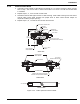
4-3.10 Lockout Valves
Thelockoutvalvewithlimitswitchmustbeinstalledinthedischargepipenetwork,downstreamofallcyl‐
inders,checkvalves,andselectorvalves.Allvalvesshouldbeeasilyaccessible.Lockoutvalvescanbein‐
stalled in either the vertical or horizontal position using good pipe fitting practices. Place two to
three
wrapsofTeflontapeonmalethreadsofpipe.Aunionisrecommendedafterthevalvetofacilitatefuture
servicework.Thevalveshouldbelockedinthe“open”positionusingapadlock.Allvalvesmustbeelectri‐
callysupervised.
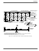
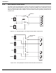
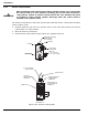
Figure 4-22 shows the lockout valve wiring diagram when the ball valve is in the fully open
position.
Figure 4-22. Wiring Diagram for Lockout Valve when Ball Valve is in Fully Open Position
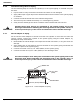
4-3.11 Pneumatic Discharge Delay
The discharge delay shall be installed with the arrow stamped on the unit pointing in the
direction of flow. The unit may be installed at any angle below horizontal. Install the discharge
delay by following the steps listed below:
1. Inspect the threads and the discharge delay for any damage.
2. Kidde recommends installing union fittings before and after the discharge delay to facilitate
future service work.
3. Ensure the piping is properly supported with pipe hangers prior to installing the discharge
delay.
4. Bushings or bell reducer fittings may be used to connect to 1/2-inch (DN15) piping. The
discharge delay connections are 3/4-inch (DN20).
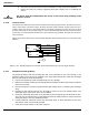
5. Install the discharge delay with arrow stamped on the unit pointing in the direction of flow.
The unit may be installed at any angle below horizontal. Kidde prefers to always install the
discharge delay in the fully pendent position.
6. Provide sufficient clearance around the discharge delay to allow operation of the lever
operated or other control head provided.
7. Verify the control head is in the "SET" position.
CAUTION
All valves must be installed with the arrow on the valve body pointing in the
direction of flow.
1
2
3
4
5
6
7
8
Brown
Purple
Yello w
Orange
Blue
Red
GND
NC
C
NO
NC
C
NO
Switch
#1
Upper
Switch
#2
Upper