
User's Manual

Installation
P/N 81-CO2MAN-001 4-25 September 2013
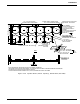
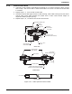
4-3.8 Discharge Head to Cylinder Valve
Install the discharge head as follows:
1. Wipe off cylinder valve sealing surface.
2. Verify that both O-rings within the discharge head are installed in the mating surface
grooves at the bottom of the swivel nut cavity. O-rings must be free of dirt or other
contaminants. The O-rings have been lightly greased at the factory and should not require
further greasing.
3. Make certain the pilot orifice located between the inner and outer O-ring is unobstructed.
4. Make certain the discharge port is clean and unobstructed.
5. Install discharge head on cylinder valve. Tighten securely.
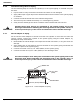
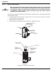
4-3.9 Check Valves and Directional (Stop) Valves
4-3.9.1 2-inch AND SMALLER CHECK VALVES AND DIRECTIONAL (STOP) VALVES
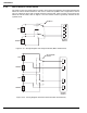
Install the 2-inch (DN50) or smaller diameter directional (stop) valves or check valves by
following the steps listed below:
1. Inspect the valves to verify the threads are not damaged.
2. Use high pressure air, nitrogen, or CO
2
to verify the valves allow flow in the direction shown
by the arrow on the valve body.
3. Kidde recommends installing union fittings before and after the valves to facilitate future
service work.
4. Apply Teflon tape or pipe dope to the piping male threads.
5. Valves can be installed horizontally or vertically.
6. Ensure the piping is properly supported with pipe hangers prior to installing the valves.
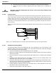
4-3.9.2 2-1/2 inch AND LARGER CHECK VALVES AND DIRECTIONAL (STOP) VALVES
Install the 2-1/2 inch (DN65) and larger diameter direction (stop) valves and check valves by
following the steps listed below:
1. Inspect the gaskets and valve assemblies for damage.
2. Use high pressure air, nitrogen, or CO
2
to verify the valves allow flow in the direction shown
by the arrow on the valve body.
3. Weld the flange connections to the piping in accordance with the ASME B31 Boiler &
Pressure Vessel Code.
4. Align the valve body with the flanges, insert gaskets between the valve body and each
flange and insert the bolts through the bolt holes.
5. Tighten the hex nuts.
a. Valves can be installed horizontally or vertically.
WARNING
The discharge head must be securely connected into the system piping. Never
attach the discharge heads to the cylinder valves until the cylinders are secured
in brackets or racking. Under no circumstances is the discharge head to remain
attached to the cylinder valve after removal from service, handling, storage, or
during shipment. Failure to follow these instructions could result in serious
bodily injury, death, or property damage.
CAUTION
All valves must be installed with the arrow on the valve body pointing in the
direction of flow.