
User's Manual

Installation
September 2013 4-4 P/N 81-CO2MAN-001
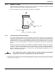
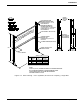
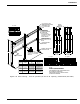
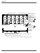
4-3.3 Discharge Manifold
Securely support the discharge manifold. The manifold must be installed such that it is level
and the inlets are aligned to connect with the cylinder valve discharge head.
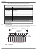
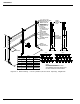
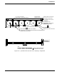
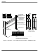
Figure 4-1. Typical Manifold Layout
Note: Not FM Approved.
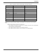
Table 4-2. Maximum Pipe Hanger and Support Design Load Ratings
Applicable to all pipe support assembly components including pipe attachment, rod,
fixtures, clamps, bolts and nuts, and building structure attachments.
Nominal Pipe Size Ratings at Normal Temperature Range*
3/8 in. (DN10) 150 lbs. (65 kg)
1/2 in. (DN15) 150 lbs. (65 kg)
3/4 in. (DN20) 150 lbs. (65 kg)
1 in. (DN25) 150 lbs. (65 kg)
1-1/4 in. (DN32) 150 lbs. (65 kg)
1-1/2 in. (DN40) 150 lbs. (65 kg)
2 in. (DN50) 150 lbs. (65 kg)
2-1/2 in. (DN65) 170 lbs. (75 kg)
3 in. (DN80) 210 lbs. (95 kg)
3-1/2 in. (DN90) 250 lbs. (110 kg)
4 in. (DN100) 300 lbs. (135 kg)
*Normal temperature range is -20
° F to 650° F (-29° C to 343° C) for carbon steel.
Extracted from MSS SP-58, 1993, with permission of the publisher, the Manufacturers
Standardization Society.
DISCHARGE HEAD
FLEX HOSE
STEPPED MANIFOLD
LOCKOUT VALVE
MECHANICAL TIME DELAY
WITH LEVER OPERATED
CONTROL HEAD
PRESSURE OPERATED
SIREN
CONTROL HEAD