
User's Manual

Installation
P/N 81-CO2MAN-001 4-3 September 2013
1
Extracted from FSSA Pipe Design handbook, Second Edition, with permission of the publisher,
FSSA.
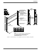
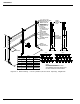
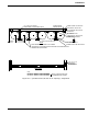
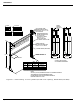
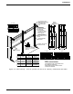
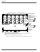
Additional Pipe Hanger and Support Considerations:
• Riser supports shall take into consideration the weight of the entire riser including pipe,
valves and other concentrated loads
• Pipe supports shall be located at each change in direction
• Pipe supports shall be located as close as possible to concentrated loads
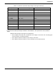
Table 4-1. Maximum Horizontal Pipe Hanger and Support Bracing
1
Pipe Size Distance Between Supports Rod Diameter
1/4 in. (DN06) 7 ft. (2.1 m) 3/8 in.
1/2 in. (DN15) 7 ft. (2.1 m) 3/8 in.
3/4 in. (DN20) 7 ft. (2.1 m) 3/8 in.
1 in. (DN25) 7 ft. (2.1 m) 3/8 in.
1-1/4 in. (DN32) 7 ft. (2.1 m) 3/8 in.
1-1/2 in. (DN40) 9 ft. (2.7 m) 3/8 in.
2 in. (DN50) 10 ft. (3 m) 3/8 in.
2-1/2 in. (DN65) 11 ft. (3.4 m) 1/2 in.
3 in. (DN80) 12 ft. (3.7 m) 1/2 in.
4 in. (DN100) 14 ft. (4.3 m) 5/8 in.
5 in. (DN125) 16 ft. (4.9 m) 5/8 in.
6 in. (DN150) 17 ft. (5.2 m) 3/4 in.
8 in. (DN200) 19 ft. (5.8 m) 3/4 in.