
User's Manual

Design
P/N 81-CO2MAN-001 3-71 September 2013
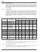
The actuating cable shall be housed in a protective casing, such as EMT or pipe, and corner
pulleys (Part No. 81-803808-000 for watertight applications or WK-844648-000 for industrial
applications) shall be used at each change in direction. It is not accept to bend the EMT. See
Table 3-12 for corner pulley quantity and cable length limitations.
Cable Pull stations shall not require a pull of more than 40 lb.(178 N) force or a movement of
more than 14" (356 mm) to actuate the system.
3-13.4.2.1 Tandem Control Heads
For actuation of two or more adjacent pilot cylinders, cable operated control heads may be
connected in tandem from a single pull station. A cable housing (See Paragraph 2-3.3.6) shall
be installed between each control head to protect the cable.
3-13.4.2.2 Multiple Pull Stations
Either the Tee Pulley (Part No. 83-843791-000) or the Dual Pull Mechanism (Part No.
81-840058-000) will allow multiple pull stations to be used with a single cable operated control
head. Each device counts as one corner pulley. The cable length from each pull station to the
control head may not exceed the maximum cable length specified in Table 3-12.
3-13.4.2.3 Multiple Cylinder Banks
The Dual Pull Equalizer (Part No. 81-840051-000) allows a single pull station to operate two
control heads. The Equalizer counts as one corner pulley. The cable length from each pull
station to the control head may not exceed the maximum cable length specified in Table 3-12.
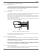
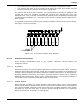
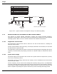
3-13.4.3 PNEUMATIC HEAT DETECTOR OPERATED ACTUATION
Pneumatic heat detection systems provide a fully mechanical means of automatic actuation.
Heat Actuated Devices (HAD) are to be installed in an anticipated path of convective heat flow
from the fire and spaced at a maximum on-center distance of 20 ft.(6.1 m), or 15 ft.-10 in.
(4.8 m) for FM applications, for ceiling heights up to 12 ft.(3.7 m). Consult NFPA 72 for
reduction in spacing for ceiling heights greater than 12 ft. and for spacing guidelines when
different ceiling configurations are encountered. Ensure that no HAD is mounted at a location
where normal process conditions can cause temperature increases to occur at rates faster than
20°F (11°C) per minute. The HAD (See Figure 2-38) is attached to a mounting bracket for ease
of installation in industrial applications. Up to five HAD's may be connected to a single
pneumatic control head. They are connected to the control head using 1/8-in. (3 mm) copper
tubing. The tubing shall be housed in a protective casing, such as pipe or EMT.
Note: The final leg of the copper tubing system connects to the pneumatic control head by
means of 3/16-in. OD heavy wall copper tubing provided by Kidde Fire Systems. The 1/8-in.
copper tubing to the HAD's must be protected by 1/2-in. EMT or pipe.
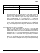
Table 3-12. Corner Pulley Quantity and Cable Length Limits
Control Head
Type
Part Number
Maximum Corner Pulleys
Maximum Cable
Length
P/N
81-803808-000
P/N
81-844648-000
ft. (m)
Cable Operated 81-979469-000 15 30 100 ft. (30m)
Electric/Cable ALL 6 30 100 ft. (30m)
Pneumatic ALL 6 30 100 ft. (30m)