
User's Manual

Design
September 2013 3-68 P/N 81-CO2MAN-001
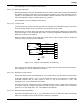
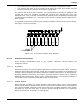
3-12.5.2 DIRECTIONAL VALVE SYSTEMS
Directional Valve Systems are used to protect multiple, separate hazards with a single agent
supply. In this arrangement, the cylinder manifold is connected to a manifold of Directional
Valves, which lead to different hazards. Upon system actuation, the appropriate valve is
opened, along with the agent cylinders, to direct the discharge to the hazard where the fire is
occurring.
In cases where the protected hazards do not require the same quantity of agent, it is possible
to discharge only a portion of the cylinder bank.
A hydraulic flow calculation shall be performed for each hazard.
3-12.5.3 ODORIZER ASSEMBLY
An odorizer assembly shall be installed downstream of each directional valve. The scent from
the odorizer will provide a post-discharge warning to any personnel entering the protected area
or adjacent areas.
3-12.5.4 ELECTRICAL CLEARANCES
All system components shall be located so as to maintain minimum clearances from live parts.
Reference NFPA 12 for additional guidance.
3-13 ACTUATION SYSTEM DESIGN
The carbon dioxide suppression system is actuated by a sub-system of components that
responds to an alarm condition and opens the carbon dioxide cylinder valves.
3-13.1 Discharge Heads
A discharge head must be attached to every CO
2
cylinder. Plain nut and grooved nut discharge
heads shall not both be used in a common manifold. See Paragraph 2-2.2 for additional
information.
3-13.2 Cylinder Actuation
Each cylinder may be actuated by either of two methods: with a control head or with manifold
back pressure.
3-13.2.1 ACTUATION WITH A CONTROL HEAD
A cylinder fitted with a Plain Nut or Grooved Nut Discharge Head, Part No. WK-872450-000 or
81-872442-000 respectively, may be actuated with any of the control heads described in
Paragraph 2-3.
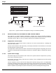
3-13.2.2 ACTUATION WITH MANIFOLD BACKPRESSURE
A cylinder fitted with a Plain Nut Discharge Head, Part No. WK-872450-000, may be actuated
by manifold back pressure, as described in Paragraph 2-2.2.
Manifold back pressure is developed when one or more cylinders are actuated with control
heads. These are pilot cylinders. The remaining cylinders, which are not fitted with control
heads and are actuated with manifold back pressure, are slave cylinders.
Since a successful system actuation is dependent on developing sufficient back pressure, the
quantity of pilot cylinders is of vital importance.