
User's Manual

Design
September 2013 3-66 P/N 81-CO2MAN-001
The CO
2
operated delay (Not FM Approved) may be located in the manifold header between
the pilot and slave cylinders (see Paragraph 3-13.2.1). Note that the Pneumatic Discharge
Delay has a 3/4-inch (DN20) NPT pipe thread, which limits the flow rate that may be passed
through the valve.
The N
2
operated delay cannot be installed in the CO
2
cylinder manifold. The N
2
operated delay
shall be installed within the N
2
actuation line terminating at the CO
2
pilot cylinders connected
to the CO
2
manifold.
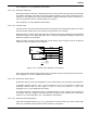
When the actuation strategy and design flow rate are such that the Delay cannot be located in
a 3/4-inch (DN20) NPT pipe section, the Delay may be used in conjunction with a Stop Valve.
In this arrangement, a Stop Valve is located in accordance with Paragraph 3-12.4.3.4 and is
controlled by a pressure-operated control head (Part No. 82-878737-000, 82-878750-000, or
82-878751-000). A side tee is installed upstream of the Stop Valve and is piped to the
Pneumatic Discharge Delay. The outlet of the Delay is connected to the pressure-operated
control head.
The Pneumatic Discharge Delay shall be fitted with a manually operated control head to provide
a by-pass. The control head shall be supervised to warn occupants that the time delay has been
by-passed.
See Paragraph 1-6.1.3 for additional information.
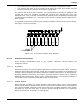
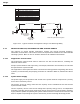
3-12.4.3.6 Pressure Operated Sirens
Pressure Operated Sirens (N
2
or CO
2
operated) are used to provide an audible alarm prior to
the start of and during discharge. The siren must be located upstream of the Pneumatic
Discharge Delay. A union should be installed at each siren connection, and a dirt trap shall be
installed after the last siren.
The total length of 1/2-inch (DN15) pipe between the cylinders and the sirens cannot exceed
250 ft. (76 m).
See Paragraph 1-6.1.3 and Paragraph 4-5.3.1 for additional information.
The N
2
pressure operated siren (P/N 90-981574-001) consumes approximately 0.5 to 0.9 lb.
(0.23 to 0.5 kg) of nitrogen per minute. Each siren driver cylinder can operate one or more
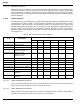
sirens. Table 3-10 indicates the number of sirens that can be installed on a line from any one
siren driver; the total length of actuation pipe that can be used must not exceed the limits
shown in this table.
108 cu. in. and 1040 cu. in. siren driver cylinders cannot be manifolded. A maximum of
two 2300 cu. in. siren drivers can be manifolded to provide up to twenty sirens on one
circuit. No other manifold combination is permitted.
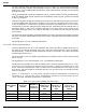
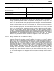
Table 3-10. Siren Driver Cylinder Actuation Limits
Pilot Cylinder
Size
Siren Part
Number
Number of
Sirens per
Siren Driver
Maximum
Length of 1/4
in. Sch. 80
Pipe
Maximum
Length of 1/4
in. Sch. 40
Pipe
Maximum Length
of 5/16 in. x
0.032 in. Wall
Tubing
108 cu. in. 90-981574-001 1 90 ft. 90 ft. 90 ft.
1040 cu. in. 90-981574-001 4 500 ft. 500 ft. 500 ft.
2300 cu. in. 90-981574-001 10 500 ft. 500 ft. 500 ft.
2 x 2300 cu. in. 90-981574-001 20 500 ft. 500 ft. 500 ft.