
User's Manual

Design
P/N 81-CO2MAN-001 3-65 September 2013
See Paragraph 2-8.5 for additional information
3-12.4.3.2 Discharge Indicators
Discharge Indicators (Part No. 81-967082-000) are used to show that the system has operated
and needs recharging. The device must be located upstream of any flow-controlling valves,
typically at the capped end of the manifold header. Multiple indicators may be necessary if a
valve arrangement results in isolated groups of cylinders.
See Paragraph 2-8.6 for additional information.
3-12.4.3.3 Lockout Valve
Lockout Valves are used to manually prevent flow of agent to the distribution piping. The valve
shall be located downstream of all cylinders and upstream of all nozzles.
Model the lock out valves within the hydraulic calculation program by adding the corresponding
equivalent length to the applicable pipe node. Contact the Application Engineering team at
Kidde Fire Systems for assistance.
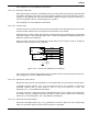
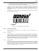
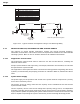
When providing a lockout valve fitted with a limit switch, refer to Figure 3-10 for wiring the
release circuit(s) through the limit switches.
Figure 3-10. Lockout Valve Release Circuit Wiring
The Lockout Valve shall be supervised to warn occupants that the system has been locked out.
See Paragraph 1-6.1.4 for additional information.
3-12.4.3.4 Directional (Stop) Valves
Directional (Stop) Valves (See Paragraph 2-5 for Part Numbers) may be used for two purposes.
In Multiple Hazard Systems, two or more Directional Valves are arranged to isolate the
protected hazards and to allow agent to flow to only one hazard at a time. See
Paragraph 3-12.5.2 for additional information.
For safety purposes, a single Stop Valve, located downstream of all cylinders and upstream of
all nozzles, may be arranged to prevent the flow of agent to the nozzles until a secondary
action occurs. See Paragraph 1-6.1.4 for additional information.
3-12.4.3.5 Pneumatic Discharge Delays
Pneumatic Discharge Delays (N
2
or CO
2
operated) are used to delay the start of discharge
while an evacuation signal is given and the enclosure is prepared.
1
2
3
4
5
6
7
8
Brown
Purple
Yello w
Orange
Blue
Red
GND
NC
C
NO
NC
C
NO
Switch
#1
Upper
Switch
#2
Upper