
User's Manual

Design
September 2013 3-64 P/N 81-CO2MAN-001
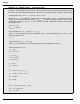
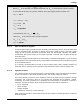
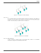
Figure 3-9. Example of a "Main and Reserve" "End" Manifold
3-12.4.2 MANIFOLD PIPE SELECTION
A cylinder manifold may be designed by either of two methods: Single Pipe Size or Stepped
Pipe Size. Each approach has its own benefits with respect to cost/ease of fabrication, flow
resistance, and developed back pressure.
3-12.4.2.1 Single Pipe Size Manifolds
A manifold may be fabricated from a single pipe size that is appropriate for the flow rate of the
entire cylinder bank. This design allows for the maximum flow rate and simpler fabrication.
However, large pipe sizes will result in lower manifold pressures, adversely affecting actuation
of multiple cylinder systems. See Paragraph 3-13 for information regarding actuation.
Single size pipe manifolds may be best suited to Multiple Hazard Systems using Directional
(Stop) Valves. In such cases, it is recommended to actuate the carbon dioxide cylinders first
and to operate the appropriate Directional (Stop) Valve only after completing the time delay
period. This sequence provides an opportunity to develop sufficient manifold pressure for
complete system actuation (See Paragraph 3-8).
3-12.4.2.2 Stepped Pipe Size Manifolds
A manifold may be fabricated from multiple pipe sizes, where the size of each pipe section is
appropriate for the quantity of cylinders upstream of the section. This design allows for the
maximum manifold back pressure to be developed. See Paragraph 3-13 for information
regarding actuation.
3-12.4.3 MANIFOLD OBJECTS
A manifold generally includes several control valves and safety devices. Familiarity with the
principles of System Actuation, as outlined in Paragraph 3-13, may be necessary to fully
understand the purposes of the following devices. All devices shall be located, installed, or
suitably protected so that they are not subject to mechanical, chemical, or other damage that
would render them inoperative.
3-12.4.3.1 Safety Outlets
Safety Outlets (Part No. 81-803242-000) are used to provide a pressure relief device where a
valve arrangement (i.e., Time Delay, Stop Valve, Lock-Out Valve, etc.…) introduces sections
of closed piping. The device may be located anywhere within the closed section.