
User's Manual

Design
September 2013 3-60 P/N 81-CO2MAN-001
The weight of the agent supply, racking, piping, and other equipment shall not exceed the
maximum load rating of the supporting structure(s).
The cylinders must be located in an environment where ambient storage temperatures shall
be:
• 0°F (-18°C) to 130°F (54°C) for total flooding systems
• 32°F (0°F) to 120°F (49°C) for local application or combination systems
External heating or cooling may be required to maintain this temperature range.
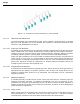
3-11.4 Single and Double Cylinder Arrangements
For installation of one or two cylinders, simple cylinder straps are used to secure the cylinders.
A 2 ft. (0.6 m) wide service aisle shall be maintained. Reference Paragraph 2-2.6.1 for
component descriptions and Paragraph 4-3.5 for installation information.
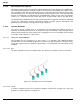
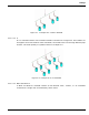
3-11.5 Multiple Cylinder Arrangements
For installation of three or more cylinders, two different styles (1 side x 1 row; 1 side x 2 rows)
of framing arrangements are available to provide flexibility of installation. A 2 ft. (0.6 m) wide
service aisle shall be maintained in front of all cylinder rows. Reference Paragraph 2-2.6.2 for
component descriptions and Paragraph 4-3.5 for installation information.
3-12 MANIFOLD AND PIPE NETWORK DESIGN
The discharge network can be broken into two distinct sections: the cylinder manifold and the
distribution network.
3-12.1 Pipe and Fitting Specifications
Pipe and tube used in the discharge network shall be in accordance with NFPA 12, current
edition.
Pipe that does not meet the specifications in Paragraph 3-12.1.1 shall be designed in
accordance with ASME B31.1, Power Piping Code, current edition and the requirements of NFPA
12, current edition. The internal pressure for this calculation shall be 2800 psi (19.3 MPa).
The Piping Design Handbook For Use With Special Hazard Fire Suppression Systems, published
by the Fire Suppression Systems Association (FSSA), is one resource that may be consulted
for the allowable working pressures for various pipe and tube materials and for guidance on
pipe support selection.
3-12.1.1 PIPE SPECIFICATIONS
Material Specification:
• Black or galvanized steel pipe shall be ASTM A-53 seamless or electric welded, Grade A or
B; or ASTM A 106, Grade A, B, or C.
• Stainless steel pipe shall be TP304 or TP316 for threaded connections, or TP304, TP316,
TP304L, or TP316L for welded connections.
• Furnace butt-weld ASTM A-53, ASTM A120, and ordinary cast iron pipe shall not be used.
• Flexible piping system components shall have a minimum burst pressure of 5,000 psi (34.5
MPa).
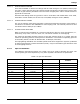
Schedule:
• Pipe sizes 3/4-inch (DN20) NPT and smaller may be Schedule 40 or greater.
• Pipe sizes 1-inch (DN25) through 4-inch (DN100) NPT shall be a minimum of Schedule 80.