
User's Manual


Design
September 2013 3-50 P/N 81-CO2MAN-001
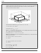
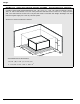
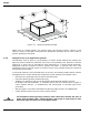
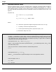
Figure 3-5. Nozzle Placement Example
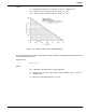
When liquid or coated hazards are present within the assumed volume, Table 3-4 and
Table 3-5 shall be consulted to determine the appropriate discharge rate for each nozzle to
prevent splashing of the liquid.
3-6.4 Safeguards for Local Application Systems
Consideration shall be given to the possibility of carbon dioxide drifting and settling into
adjacent places outside the protected area and to the possibility that personnel could be
trapped in or enter into an atmosphere made hazardous by a carbon dioxide discharge.
Safeguards shall be provided to ensure prompt evacuation, to prevent entry into such
atmospheres and to provide means for prompt rescue of any trapped personnel. Personnel
training shall be provided.
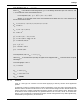
If personnel could be in the protected space at any time, the following safety devices shall be
integrated into the carbon dioxide fire suppression system (Reference Paragraph 1-6.1):
• Pneumatic pre-discharge alarm (Pressure Operated Siren)
• Pneumatic Discharge delay (Discharge Delay)
• Addition of a distinctive odor to the discharging carbon dioxide (Odorizer Part No.
81-897637-000 and 10030080), or automatic alarms that are activated by an oxygen or
carbon dioxide detector, or establishment and enforcement of confined space entry
procedures
• Warning signs in accordance with NFPA 12 (Warning Signs Part No. 06-231866-85X)
• Carbon dioxide system Lock-Out valve (Lockout Valves)
WARNING
The Pneumatic Discharge Delay and any other valve that controls the flow of
agent shall be fitted with a manual bypass control that is supervised to alert
personnel when the device is in the bypass mode.
W
2 ft.
2 ft.
2 ft.
L
H