
User's Manual

Design
September 2013 3-42 P/N 81-CO2MAN-001
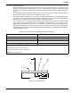
EXAMPLE 10 - LOCAL APPLICATION: RATE-BY-AREA - Tankside Nozzles
Consider a quench tank with liquid surface dimensions of 3 ft. x 7 ft. . Minimize carbon dioxide
and nozzle requirements while using a tankside nozzle location. Calculate the quantity of nozzles,
minimum flow rate and the minimum carbon dioxide supply for the hazard.
From Equation (21):
Where is the Quantity Of Nozzle Rows and is the Width of the Protected Area.
= 4
= 3 4
= 0.75
1 row
From Equation (22):
Where is the Width of the Nozzle Coverage Area.
= 3 1
= 3 ft.
From Equation (23):
Where is the Maximum Nozzle Coverage Length and is the Maximum Nozzle Coverage
Area.
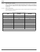
From Table 3-7A:
= 11.75
ft.
2
= 11.75 3
= 3.9 ft.
From Equation (24):
Where is the Quantity of Nozzles per Row and is the Length of the Protected Surface.
=
= 7 3.9
= 1.8
2 nozzles
W
L
N
w
w 4=
N
w
w
N
w
w
N
w
N
w
N
w
s
w
wN
w
=
s
w
s
w
wN
w
=
s
w
s
w
S
lmax
A
max
S
w
=
s
lmax
A
max
A
max
S
lmax
A
max
S
w
=
s
lmax
s
lmax
N
l
lS
lmax
=
N
l
l
N
l
l
S
lmax
N
l
N
l
N
l