
User's Manual

Design
September 2013 3-40 P/N 81-CO2MAN-001
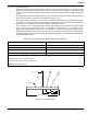
3-6.2.2.3 Nozzle Coverage and Carbon Dioxide Requirements
Whereas overhead nozzles are based on "side of square" coverage (one dimension), tankside
coverage is based on surface area (two dimensions). Since the Type "L" nozzle has a limited
discharge thrust, it is necessary to maintain a maximum dimension on all sides of the coverage
area. The following limits shall be observed:
• Maximum surface area per Table 3-7 or Table 3-8
• Maximum throw (forward): 4 ft. (1.22 m)
• Maximum distance between adjacent nozzles: 5 ft. (1.52 m)
• Maximum distance between first/last nozzle and corner of hazard area: 2-1/2 ft. (0.76 m)
Assuming a row of nozzles on each side of the hazard surface, the maximum hazard width is
8 ft. (2.44 m) for systems using tankside nozzles only. For hazards that exceed this limitation,
additional overhead nozzles may be used to provide coverage of the area along the centerline
of the protected surface. When overhead nozzles are used in conjunction with tankside nozzles,
the flow rate for the overhead portion shall be calculated in accordance with
Paragraph 3-6.3.1. The total discharge rate for the hazard shall be the sum of the tankside
( ) and overhead ( ) portions.
The quantity of tankside nozzles may be calculated using Equations (21) through (27).
(Equation 21)
(US Units)
or
Where:
= Number of nozzle rows
= Width of protected area, ft. (m)
(Equation 22)
Where:
= Width of nozzle coverage area, ft. (m)
= Width of protected area up to 8 ft. (2.44 m), ft. (m)
= from Equation (21) rounded up to the next whole number
(Equation 23)
Where:
= Maximum length of nozzle coverage area, ft. (m)
= 11.75
ft.
2
(1.092 m
2
) for liquid surfaces; 16-1/2 ft.
2
(1.533 m
2
) for
coated surfaces
= Width of nozzle coverage area from Equation (22), ft. (m)
q
TS
q
OH
N
w
w 4=
N
w
w 1.22=
N
w
w
S
w
wN
w
=
S
w
w
N
w
N
w
S
lmax
A
max
S
w
=
S
lmax
A
max
s
w