
User's Manual

Design
P/N 81-CO2MAN-001 3-35 September 2013
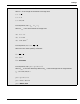
3-6.2.1.2 Nozzle Positioning
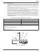
Overhead nozzles shall be aimed and located over the protected area in accordance with
Table 3-6 and as demonstrated in Figure 3-3. The aiming factor is multiplied by the total width
of the protected area to determine the location of the aiming point from the edge nearest the
nozzle.
The height used in determining the flow rate of the nozzle shall be the distance from the aiming
point on the hazard to the face of the nozzle (See Figure 3-3).
The nozzle shall be located so as to be free of possible obstructions that could interfere with
the delivery of carbon dioxide to the protected surface and so as to develop an extinguishing
atmosphere over coated stock extending above a protected surface.
If air currents, wind, or forced drafts are present, discharged carbon dioxide may be prevented
from reaching the protected surface in adequate concentrations to extinguish a fire.
Additionally, sufficient air velocity may cause liquid to splash and escape the hazard area,
potentially spreading a fire. In the event of such circumstances, nozzles shall be located so as
to compensate for these effects and consideration shall be given to installing additional nozzles
outside the hazard area.
Figure 3-3. Nozzle Aiming
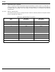
Table 3-6. Aiming Factors for Angular Placement of Nozzles
1
Discharge Angle
2
Aiming Factors
3
45 - 60 1/4
60 - 75 1/4 - 3/8
75 - 90 3/8 - 1/2
90 (perpendicular) 1/2 (center)
1
Based on 6-inch (152 mm) freeboard.
2
Degrees from plane of hazard surface.
3
Fractional amount of nozzle coverage area.
Note: Also see Figure 3-3.
D
75-90°
60-75°
45-60°
PROTECTED SURFACE
(HEIGHT)
(HEIGHT)
(HEIGHT)
DISCHARGE NOZZLE
(NOZZLE COVERAGE AREA)
1/2D
3/8D
1/4D