
User's Manual

P/N 81-CO2MAN-001 xiii September 2013
TABLE OF CONTENTS (CONT.)
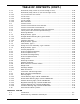
3-16.4.4 Carbon Dioxide Supply ..........................................................................3-82
3-16.4.5 Actuation............................................................................................. 3-82
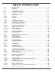
CHAPTER 4 INSTALLATION
4-1 Introduction......................................................................................... 4-1
4-2 General Installation Requirements........................................................... 4-1
4-3 Installation of Suppression Systems ........................................................4-1
4-3.1 Discharge Pipe and Fittings .................................................................... 4-1
4-3.2 Pressure Operated Actuation Pipe, Tubing and Fittings ............................... 4-2
4-3.3 Discharge Manifold................................................................................ 4-4
4-3.4 Manifold “Y” Fitting................................................................................ 4-5
4-3.5 Carbon Dioxide Cylinder Assemblies ........................................................ 4-5
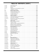
4-3.6 Flexible Discharge Hose to Piping ........................................................... 4-24
4-3.7 Swivel Adapter to Piping ........................................................................ 4-24
4-3.8 Discharge Head to Cylinder Valve............................................................ 4-25
4-3.9 Check Valves and Directional (Stop) Valves .............................................. 4-25
4-3.9.1 2-inch and Smaller Check Valves and Directional (Stop) Valves................... 4-25
4-3.9.2 2-1/2 inch and Larger Check Valves and Directional (Stop) Valves...............4-25
4-3.10 Lockout Valves ..................................................................................... 4-26
4-3.11 Pneumatic Discharge Delay ....................................................................4-26
4-3.12 Discharge Nozzles................................................................................. 4-27
4-4 Actuation Systems ................................................................................ 4-27
4-4.1 Lever Operated Control Head..................................................................4-27
4-4.2 Cable Operated Actuation System Components......................................... 4-27
4-4.3 Cable Operated Control Head.................................................................. 4-29
4-4.4 Pull Boxes............................................................................................ 4-29
4-4.5 Main to Reserve Transfer Switch .............................................................4-30
4-4.6 Tandem Control Head............................................................................ 4-31
4-4.7 Electric Control Heads............................................................................4-32
4-4.8 Electric and Cable Operated Control Heads ............................................... 4-33
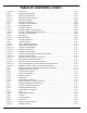
4-4.9 Pneumatic Heat Actuated Detection (HAD) System Components..................4-35
4-4.9.1 HAD....................................................................................................4-35
4-4.9.2 Tubing................................................................................................. 4-36
4-4.9.3 Manometer Test Procedure..................................................................... 4-38
4-4.9.4 Control Head Vent Test..........................................................................4-38
4-4.9.4.1 To Test Pneumatic Detectors And/or System Tubing For Tightness............... 4-39
4-4.9.4.2 Other Use For Manometer ...................................................................... 4-39
4-4.9.5 Heat Collector ......................................................................................4-39
4-4.10 Pneumatic Control Head.........................................................................4-40
4-4.11 Nitrogen Actuation Station ..................................................................... 4-42
4-4.11.1 Installation of Nitrogen Cylinder, P/N WK-877940-000, and Mounting Bracket, P/N
WK-877845-0004-42
4-4.11.2 Nitrogen Pilot Cylinder Installation, 1040 cu. in. and 2300 cu. in., P/Ns 90-101040-
000 and 90-102300-1004-43
4-4.12 Pressure Operated Control Heads............................................................ 4-44
4-4.13 Lever and Pressure Operated Control Heads ............................................. 4-44
4-5 Auxiliary Components............................................................................ 4-45
4-5.1 Pressure Operated Switches ...................................................................4-45