P/N 81-CO2MAN-001 September 2013 Engineered Carbon Dioxide (CO2) Fire Suppression Systems Design, Installation, Operation and Maintenance Manual R LISTED UL Listing File No.
FOREWORD Note: This Kidde Fire Systems Engineered Carbon Dioxide (CO2) Fire Suppression System Design, Installation, Operation, and Maintenance manual, P/N 81-CO2MAN-001, is for use only by qualified and factory-trained personnel with working knowledge of applicable standards such as NFPA, as well as a working knowledge of Kidde Fire Systems Engineered Carbon Dioxide (CO2) Fire Suppression System. Kidde Fire Systems does not authorize or recommend use of this Manual by others.
THIS PAGE INTENTIONALLY LEFT BLANK.
SAFETY SUMMARY The Kidde Fire Systems Engineered Carbon Dioxide (CO2) Fire Suppression System, uses pressurized equipment, and therefore you MUST notify personnel responsible or who may come into contact with the Engineered Carbon Dioxide (CO2) Fire Suppression System, of the dangers associated with the improper handling, installation, maintenance, or use of this equipment.
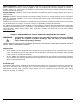
Moving Cylinders: Cylinders must be shipped compactly in the upright position, and properly secured in place. Cylinders must not be rolled, dragged or slid, nor allowed to be slid from tailgates of vehicles. A suitable hand truck, fork truck, roll platform or similar device must be used while maintaining properly secured cylinders at all times. Rough Handling: Cylinders must not be dropped or permitted to strike violently against each other or other surfaces.
Installation THIS SEQUENCE FOR CYLINDER INSTALLATION MUST BE FOLLOWED AT ALL TIMES: 1. Position cylinder(s) in designed location and secure with cylinder bracket(s). 2. Remove safety (shipping) cap and actuation port protection cap. 3. Attach flex loops or swivel adapter to discharge heads. Connect assembly to system piping. Then attach assembly to cylinders. WARNING 4. Verify control head(s) are in the set position. WARNING 5.
THIS PAGE INTENTIONALLY LEFT BLANK.
TABLE OF CONTENTS Foreword ....................................................................................................... i Terms and Abbreviations ................................................................................. i Material Safety Data Sheets ............................................................................. i Safety Summary............................................................................................. iii Definitions .......................................
TABLE OF CONTENTS (CONT.) 2-3.1 2-3.2 2-3.3 2-3.3.1 2-3.3.2 2-3.3.3 2-3.3.4 2-3.3.5 2-3.3.6 2-3.3.7 2-3.3.8 2-3.3.9 2-3.4 2-3.4.1 2-3.4.2 2-3.4.3 2-3.5 2-3.5.1 2-3.6 2-3.6.1 2-3.6.2 2-3.6.3 2-3.6.4 2-3.6.5 2-3.6.5.1 2-3.6.5.2 2-3.6.6 2-3.7 2-3.7.1 2-3.7.2 2-3.7.3 2-3.8 2-3.8.1 2-3.8.1.1 2-3.8.1.2 2-3.8.1.3 2-3.8.2 2-3.8.3 2-4 2-4.1 2-4.2 2-4.3 2-4.3.1 2-4.3.2 2-4.3.3 2-4.3.4 2-5 September 2013 Lever-Operated Control Head .................................................................
TABLE OF CONTENTS (CONT.) 2-5.1 2-5.2 2-5.2.1 2-5.2.2 2-5.2.3 2-5.2.4 2-5.2.5 2-6 2-6.1 2-6.2 2-6.3 2-6.4 2-7 2-7.1 2-7.1.1 2-7.1.2 2-7.1.3 2-7.2 2-7.3 2-7.3.1 2-7.4 2-8 2-8.1 2-8.2 2-8.3 2-8.4 2-8.5 2-8.6 2-8.7 2-8.8 2-8.9 2-8.10 2-8.11 2-9 2-9.1 2-9.2 2-9.2.1 2-9.2.2 2-9.2.3 2-9.2.4 2-9.2.5 2-9.2.6 2-10 Directional (Stop) Valves (1/2-inch through 2-inch) ................................... 2-46 Directional (Stop) Valves (2 1/2-inch through 4-inch) ................................
TABLE OF CONTENTS (CONT.) 3-3 3-4 3-4.1 3-4.2 3-4.3 3-5 3-5.1 3-5.1.1 3-5.1.2 3-5.1.3 3-5.1.4 3-5.2 3-5.2.1 3-5.2.2 3-5.2.2.1 3-5.2.3 3-5.2.4 3-5.2.4.1 3-5.2.4.2 3-5.2.4.3 3-5.2.5 3-5.3 3-5.3.1 3-5.3.2 3-5.3.2.1 3-5.3.2.2 3-5.3.2.3 3-5.3.3 3-5.4 3-5.4.1 3-5.4.2 3-5.4.3 3-6 3-6.1 3-6.1.1 3-6.1.2 3-6.1.3 3-6.1.4 3-6.2 3-6.2.1 3-6.2.1.1 3-6.2.1.2 3-6.2.2 3-6.2.2.1 3-6.2.2.2 3-6.2.2.3 3-6.3 September 2013 Design for Safety ..................................................................................
TABLE OF CONTENTS (CONT.) 3-6.3.1 3-6.3.2 3-6.3.3 3-6.4 3-7 3-8 3-9 3-10 3-10.1 3-10.2 3-10.3 3-10.3.1 3-10.3.2 3-10.3.2.1 3-10.3.2.2 3-11 3-11.1 3-11.2 3-11.3 3-11.4 3-11.5 3-12 3-12.1 3-12.1.1 3-12.1.2 3-12.1.3 3-12.1.4 3-12.2 3-12.3 3-12.4 3-12.4.1 3-12.4.1.1 3-12.4.1.2 3-12.4.1.3 3-12.4.1.4 3-12.4.2 3-12.4.2.1 3-12.4.2.2 3-12.4.3 3-12.4.3.1 3-12.4.3.2 3-12.4.3.3 3-12.4.3.4 3-12.4.3.5 3-12.4.3.6 3-12.4.3.7 3-12.4.3.8 P/N 81-CO2MAN-001 Assumed Enclosure ..................................................
TABLE OF CONTENTS (CONT.) 3-12.4.3.9 3-12.5 3-12.5.1 3-12.5.2 3-12.5.3 3-12.5.4 3-13 3-13.1 3-13.2 3-13.2.1 3-13.2.2 3-13.3 3-13.3.1 3-13.3.2 3-13.3.3 3-13.4 3-13.4.1 3-13.4.2 3-13.4.2.1 3-13.4.2.2 3-13.4.2.3 3-13.4.3 3-13.4.3.1 3-13.4.3.2 3-13.4.4 3-13.4.5 3-13.4.5.1 3-13.4.5.2 3-14 3-14.1 3-14.2 3-14.3 3-14.4 3-14.5 3-14.6 3-14.7 3-15 3-15.1 3-15.2 3-16 3-16.1 3-16.2 3-16.3 3-16.4 3-16.4.1 3-16.4.2 3-16.4.3 September 2013 Odorizers.........................................................................
TABLE OF CONTENTS (CONT.) 3-16.4.4 3-16.4.5 Carbon Dioxide Supply .......................................................................... 3-82 Actuation ............................................................................................. 3-82 CHAPTER 4 INSTALLATION 4-1 Introduction ......................................................................................... 4-1 4-2 General Installation Requirements...........................................................
TABLE OF CONTENTS (CONT.) 4-5.2 4-5.3 4-5.3.1 4-5.3.2 4-5.4 4-5.5 4-5.6 4-6 4-7 4-7.1 4-7.2 4-7.3 4-7.4 4-7.5 4-7.6 4-7.7 4-7.8 4-7.9 Pressure Operated Trip .......................................................................... 4-47 Pressure Operated Sirens....................................................................... 4-48 CO2 Pressure Operated Siren ................................................................. 4-48 N2 Pressure Operated Siren ...............................................
TABLE OF CONTENTS (CONT.) 6-5.4 6-5.4.1 6-5.4.2 6-5.4.3 6-5.4.4 6-6 6-6.1 6-6.1.1 6-6.1.2 6-6.2 6-6.3 6-6.4 6-7 6-8 6-8.1 6-8.2 6-9 6-9.1 6-9.2 Pneumatic Detection System Tests .......................................................... 6-8 Pneumatic Control Head Test - Pressure Setting ........................................ 6-8 Control Head Vent Test .......................................................................... 6-9 Test for Leakage of System Tubing and Detectors .............................
TABLE OF CONTENTS (CONT.) B-4 B-4.1 B-4.2 B-5 B-5.1 B-5.2 B-6 B-7 B-7.1 B-7.1.1 B-7.1.2 B-7.2 B-8 B-8.1 B-8.2 B-8.3 B-8.4 B-8.5 Pneumatic Transmitter .......................................................................... B-4 Description .......................................................................................... B-4 Installation .......................................................................................... B-5 Pneumatic Control Head (1-inch, 40-second) ........................
LIST OF FIGURES Figure 2-1 2-2 2-3 2-4 2-5 2-6 2-7 2-8 2-9 2-10 2-11 2-12 2-13 2-14 2-15 2-16 2-17 2-18 2-19 2-20 2-21 2-22 2-23 2-24 2-25 2-26 2-27 2-28 2-29 2-30 2-31 2-32 2-33 2-34 2-35 2-36 2-37 2-38 2-39 2-40 2-41 2-42 2-43 2-44 2-45 2-46 2-47 2-48 2-49 2-50 2-51 2-52 2-53 Name Page Number 25 through 50 lb. Carbon Dioxide Cylinders, Bent Siphon Tube .................................. 2-2 75 and 100 lb. Carbon Dioxide Cylinder, Straight Siphon Tube ...................................
LIST OF FIGURES (CONT.) Figure 2-54 2-55 2-56 2-57 2-58 2-59 2-60 2-61 2-62 2-63 2-64 2-65 2-66 2-67 2-68 2-69 2-70 2-71 2-72 2-73 2-74 2-75 2-76 2-77 2-78 2-79 2-80 2-81 2-82 2-83 2-84 2-85 2-86 2-87 2-88 2-89 2-90 2-91 2-92 2-93 2-94 3-1 3-2 3-3 3-4 3-5 3-6 3-7 3-8 3-9 3-10 3-11 3-12 Name Page Number Lockout Valves without Limit Switches .................................................................... 2-49 Lockout Valves with Lock ......................................................................
LIST OF FIGURES (CONT.) Figure 3-13 3-14 3-15 4-1 4-2 4-3 4-4 4-5 4-6 4-7 4-8 4-9 4-10 4-11 4-12 4-13 4-14 4-15 4-16 4-17 4-18 4-19 4-20 4-21 4-22 4-23 4-24 4-25 4-26 4-27 4-28 4-29 4-30 4-31 4-32 4-33 4-34 4-35 4-36 4-37 4-38 4-39 4-40 4-41 4-42 4-43 4-44 4-45 4-46 4-47 6-1 6-2 Name Page Number Pressure Trip Applications ..................................................................................... 3-77 Typical Hand Hose Line System with Rack ........................................................
LIST OF FIGURES (CONT.) Figure 6-3 7-1 7-2 B-1 B-2 B-3 B-4 B-5 B-6 B-7 B-8 B-9 B-10 B-11 Name Page Number Manometer Pneumatic Detection............................................................................ 6-8 I/2-inch Type “I” Cylinder Valve............................................................................. 7-5 5/8-inch Type “I” Cylinder Valve ............................................................................ 7-6 3-Well Mercury Check ..............................................
LIST OF TABLES Table 1-1 2-1 2-2 2-3 2-4 2-5 2-6 2-7 2-8 2-9 2-10 2-11 2-12 2-13 2-14 2-15 2-16 2-17 2-18 2-19 2-20 2-21 2-22 2-23 2-24 2-25 2-52 2-26 2-52 2-27 2-28 2-29 2-30 2-31 2-32 2-33 3-1 3-2 3-2 3-3 3-4 3-4 3-5 3-5 3-6 3-7 3-7 3-8 3-8 3-9 3-10 3-11 3-12 Name Page Number Physical Properties of Carbon Dioxide ..................................................................... 1-8 Safety Disc Information ........................................................................................
LIST OF TABLES (CONT.) Table 3-13 3-14 3-15 4-1 4-2 4-3 4-4 4-5 4-6 6-1 8-1 8-2 8-3 8-4 8-5 8-6 8-7 8-8 8-9 8-10 8-11 8-12 8-13 8-14 8-15 8-16 8-17 8-18 8-19 8-20 8-21 B-1 B-2 C-1 Name Page Number Nitrogen Pilot Line Length Limitations ..................................................................... 3-73 Equivalent Lengths of Hand Hose Line Components (US Units)................................... 3-80 Equivalent Lengths of Hand Hose Line Components (Metric Units) ..............................
General Information CHAPTER 1 GENERAL INFORMATION 1-1 INTRODUCTION The Kidde Fire Systems carbon dioxide fire suppression system is an engineered, specialhazard system utilizing a fixed pipe and nozzle distribution network, hose reels, or a combination of both. These systems provide fire protection, using carbon dioxide (CO2) as the extinguishant, designed in accordance with the National Fire Protection Association (NFPA) 12, "Standard on Carbon Dioxide Extinguishing Systems", (latest edition).
General Information WARNING Carbon dioxide is present in the atmosphere. It is also a normal product of human and animal metabolism; human life cannot be sustained if this carbon dioxide is not expelled from the body. The concentration of carbon dioxide in the air governs the rate at which the carbon dioxide produced by the human metabolism is released from the lungs. An increasing concentration in the air where humans are present, therefore, can cause serious personal injury or death.
General Information Carbon dioxide systems can also consist of hand hose lines permanently connected by means of fixed piping to a fixed supply of suppression agent. These systems are frequently provided for manual protection of small, localized equipment. Although not a substitute for a fixed system, a hose line can be used to supplement a fixed system where the hazard is accessible for manual firefighting.
General Information as well as to warn personnel not to enter the protected space after a CO2 discharge until the area has been safely ventilated. See Paragraph 2-9.2 for specific sign and location information. All personnel shall be informed that discharge of carbon dioxide gas directly at a person will endanger the person's safety by causing frostbite, eye injury, ear injury, or even falls due to loss of balance upon the impingement of the high-velocity discharging gas.
General Information 1-6.1.5 POST-RELEASE WARNINGS AND PROCEDURES After a release of carbon dioxide, provisions shall be made to prohibit entry of unprotected personnel to spaces made unsafe by a carbon dioxide discharge until the space is ventilated and appropriate tests of the atmosphere have verified that it is safe for unprotected persons to enter.
General Information discharged up through the siphon tube, valve, and distribution piping as a liquid under pressure. The liquid is transformed into gas and the resulting expansion at the discharge nozzle orifice and upon discharge a portion immediately flashes to vapor. The remaining liquid undergoes continuous evaporation and cooling and eventually solidifies as finely divided dry ice (snow) particles. The percentage of carbon dioxide converted to dry ice depends upon the temperature of the stored liquid.
General Information Industrial applications typically consist of equipment or processes where flammable liquids are involved. Examples of industrial hazards that can be protected by carbon dioxide are dip tanks, mixing tanks, spray booths, ovens and dryers, quench tanks, coating machines, wet benches, commercial fryers, and printing presses.
General Information Table 1-1. Physical Properties of Carbon Dioxide Parameter US Units Metric Units 44 44 1.524 1.524 0.1234 lb./ft.3 1.98 kg/m3 47.6 lb./ft.3 (@ 70oF) 762 kg/m3 (@ 21oC) Triple point -69.9°F / 75.1 psia -56.6°C / 518 kPa abs Sublimation temperature @ 1 atm (101 kPa abs) -109.3°F @ 1 atm -78.5°C 87.9°F 31.1°C 1071 psia 7382 kPa abs Latent heat of sublimation, @ -109.3oF (-78.5oC) 245.5 BTU/lb. 199.0 kJ/kg Latent heat of vaporization, @ 2oF (-17oC) 119.0 BTU/lb.
Component Descriptions CHAPTER 2 COMPONENT DESCRIPTIONS 2-1 FIRE SUPPRESSION SYSTEM COMPONENTS This chapter provides detailed descriptions of the components comprising the Kidde Fire Systems CO2 fire suppression system.
Component Descriptions Five cylinder and valve assemblies are available, ranging in capacity from 25 lb. to 100 lb. of carbon dioxide. The 25, 35, and 50 lb. cylinders (Figure 2-1) are equipped with a 1/2-inch discharge valve, Part. No. WK-981372-000 (Figure 2-3); the 75 and 100 lb. cylinders (Figure 2-2) have a 5/8-inch discharge valve, Part No. WK-840253-000 (Figure 2-4). WARNING The cylinders are factory-equipped with a protection cap threaded securely over the valve assembly.
Component Descriptions TYPE "I" CYLINDER VALVE THREAD FOR DISCHARGE HEAD CONTROL PORT SAFETY DISC ASSEMBLY THREAD FOR PROTECTION CAP CYLINDER MATERIALS: CYLINDER: STEEL A MATERIALS: VALVE BODY VALVE SEAT SLEEVE SLEEVE RETAINER } BRASS MAIN CHECK BRASS WITH RUBBER SEAT PILOT CHECK STAINLESS STEEL WITH RUBBER SEAT SIPHON TUBE: ALUMINUM SIPHON TUBE B PART NUMBER CYLINDER CO2 CAPACITY lbs. kg VALVE SIZE SAFETY SIPHON TUBE DISC DIM. "A" (HEIGHT) DIM. "B" (DIAMETER) in. mm in.
Component Descriptions 2-2.1.1 VALVES VALVE SEAT VALVE BODY MAIN CHECK 2-1/2 in. -14 NS-3 (FOR DISCHARGE HEAD CONNECTION) SLEEVE RETAINER SPRING DISC RETAINER 4.98 in. (127 mm) SAFETY DISC PILOT CHECK WASHER 1 in. NPT 1-1/4 in. -18 NS-3 (FOR CONTROL HEAD CONNECTION) TYPICAL CYLINDER SLEEVE TYPICAL SIPHON TUBE SIPHON TUBE THREADED IN PLACE 3/8 in.
Component Descriptions VALVE SEAT VALVE BODY MAIN CHECK 2-1/2 in. -14 NS-3 (FOR DISCHARGE HEAD CONNECTION) SLEEVE RETAINER SPRING DISC RETAINER 5.44 in. (138 mm) SAFETY DISC PILOT CHECK WASHER 1 in. NPT 1-1/4 in. -18 NS-3 (FOR CONTROL HEAD CONNECTION) TYPICAL CYLINDER SLEEVE TYPICAL SIPHON TUBE SIPHON TUBE STAKED IN PLACE Figure 2-4. 5/8-inch Type “I” Cylinder Valve 2-2.1.
Component Descriptions PERCENT OF WATER CAPACITY 60% 64% 68% 180 170 160 150 140 130 120 110 100 TEMPERATURE, F 90 88 80 70 60 50 40 30 20 10 0 -10 -20 -30 -40 0 400 200 600 800 1200 1000 1600 1400 2000 1800 2400 2200 2800 2600 3200 3000 3600 3400 3800 PRESSURE, PSIA % of H2O capacity = Rated CO2 capacity of cylinders (in lbs) x 100 0 H2O capacity of cylinders (in lbs) at 60 F Critical temperature of CO2 = 880 F Figure 2-5. Pressure vs. Temperature for CO2 Cylinders Table 2-2.
Component Descriptions 2-2.2 Discharge Heads Each cylinder and valve assembly must be equipped with a discharge head at installation to actuate the cylinder valve. The discharge head is assembled to the top of the cylinder valve and contains a spring-loaded piston which when actuated by carbon dioxide pressure is designed to depress the main check in the valve and discharge the contents of the cylinder. The piston provides the necessary mechanical advantage to open the valve's main check.
Component Descriptions PISTON PLAIN NUT DISCHARGE HEAD BALL CHECK BALL CHECK PILOT PRESSURE PATH FOR SLAVE OPERATION PILOT PRESSURE PATH IN DISCHARGE HEAD STOP CHECK STEM DISCHARGE OUTLET PILOT PRESSURE HERE WILL DISCHARGE THIS CYLINDER OUTER O-RING INNER O-RING PILOT PRESSURE PATH IN VALVE NO GROOVES IN SWIVEL NUT MAIN CHECK PILOT PORT SAFETY OUTLET PILOT CHECK TYPE “I” CYLINDER VALVE (SEE K-1050) TYPICAL SIPHON TUBE TYPICAL CYLINDER CAUTION NEVER CONNECT DISCHARGE HEAD TO CYLINDER VALVE WIT
Component Descriptions 2-5/8 in. (66 mm) PISTON SPRING 3/4 in. NPS 3-15/16 in. (100 mm) DISCHARGE OUTLET IDENTIFYING GROOVES IN SWIVEL NUT SET POSITION OPERATED POSITION 2 1/2 - 14N3 SWIVEL NUT (FOR CONNECTION TO CYLINDER VALVE) OUTER O-RING P/N WF-242466-000 STEM INNER O-RING P/N WF-242467-000 Figure 2-8. Discharge Head, Grooved Nut WARNING P/N 81-CO2MAN-001 The discharge head must be permanently connected into the system piping.
Component Descriptions PISTON GROOVED NUT DISCHARGE HEAD STOP CHECK DISCHARGE OUTLET PILOT PRESSURE HERE WILL NOT DISCHARGE THIS CYLINDER.
Component Descriptions 2-2.3 Flexible Hoses Flexible discharge hoses are used to provide the interconnection between the discharge head and the distribution manifold or piping. The hoses are made of wire-reinforced rubber. The 1/2-inch flex hose, Part No. 81-252184-000 (Figure 2-10), is used with the 25, 35, and 50 lb. cylinders. The 3/4-inch flex hose, Part No. WK-251821-000 (Figure 2-11), is used with the 75 and 100 lb. cylinders.
Component Descriptions 2-2.4 Swivel Adapter A swivel adapter, Part No. WK-934208-000 (Figure 2-12), can be substituted for a flexible hose in a single-cylinder suppression system. It is used to connect the discharge head to the distribution piping. WARNING The swivel adapter must always be connected to the system piping and to the discharge head before attaching the discharge head to the cylinder valve in order to prevent injury in the event of inadvertent carbon dioxide discharge. SWIVEL NUT 1/2 in.
Component Descriptions 2-2.6 Cylinder Mounting Hardware Straps are available for securing single or double cylinders against a wall or other supporting structure. Free standing arrangements are not available. If walls are not available, a simple free standing support can be built up from the floor. Specially designed racks are available to secure multiple cylinders in various arrangements.
Component Descriptions 2-2.6.1.2 Double Cylinder Straps The dimensions for double cylinder straps (Figure 2-15) are provided in Table 2-4. B E A R R D C Figure 2-15. Double Cylinder Straps Table 2-4. Double Cylinder Strap Dimensions Part Number Cylinder Size WK-241219-000 WK-241254-000 September 2013 A B C D E R in. mm in. mm in. mm in. mm in. mm in. mm 50 & 75 7.75 197 22.8 579 21.5 546 1.75 44.4 2.88 73.1 4.63 118 100 10.3 262 25.6 650 24.3 617 1.75 44.
Component Descriptions 2-2.6.2 MULTIPLE CYLINDER ARRANGEMENTS Three different styles of framing arrangements are available to provide flexibility of installation for installation of three or more cylinders: Arrangement A: This style (Figure 2-16) is used for a single row of cylinders, that can be either wall mounted or free standing. 50, 75 or 100 lb. SERVICING AISLE Figure 2-16.
Component Descriptions Arrangement C: This style (Figure 2-18) provides for a double row of cylinders on the same side of the framing. This arrangement can be free standing or wall mounted. It is generally used when the cylinders are to be wall mounted and sufficient space is not available to arrange them in a single row. 50, 75 or 100 lb. OMIT CYLINDER HERE FOR ODD NUMBER SERVICING AISLE Figure 2-18.
Component Descriptions Table 2-5. Framing Kits - One Row, 3 through 15 Cylinders Number of Cylinders 3 4 5 6 7 8 9 10 11 12 13 14 15 Kit Number 81-010001-XXX 003 004 005 006 007 008 009 010 011 012 013 014 015 Part No.
Component Descriptions SECURE MANIFOLD WITH PIPE CLAMP 6 - CYLINDERS KIDDE MODEL 4706 ALLOW 2 ft. (610 mm) AISLE IN FRONT OF CYLINDERS FOR SERVICING TABLE NO CYLS 6 13-5/16 in. (338 mm) WEIGH BAR P/N CYL CHANNEL P/N LENGTH 6 ft. 1-3/4 in. (1873 mm) (2) WK-271563-000 (2) WK-243796-000 SLOT FOR PIPE CLAMP WEIGHING BAR (SEE TABLE) FASTEN WITH 3/8 in. X 1 in. LONG BOLT AND NUT WEIGHING BAR BRACKET (3) WK-271567-000 - FASTEN WITH 3/8 in. X 1 in.
Component Descriptions 2-3 ACTUATION COMPONENTS Actuation of the suppression system is initiated by use of control head(s). Control heads are components that attach to the control ports of the carbon dioxide cylinder valves. The control head initiates the suppression system discharge by opening the cylinder valve's pilot check. This allows carbon dioxide to pressurize the discharge head piston, which opens the main check in the valve and discharges the contents of the cylinder.
Component Descriptions LOCKING PIN ALLOW APPROXIMATELY 2 in. (50 mm) CLEARANCE FOR OPERATION OF LEVER CLOSED BODY SEAL WIRE LEVER TO OPEN 3-3/16 in. (81 mm) SWIVEL NUT 1-1/2 in. (81 mm) SET 1-1/4 in. - 18 NF-3 FEMALE OPERATED 3 in. (76 mm) STEM Figure 2-20. Lever-Operated Control Head 2-3.2 Cable-Operated Control Head The cable-operated control head, Part No.
Component Descriptions LOCAL MANUAL RELEASE LEVER SEAL WIRE LOCKING PIN DIRECTION OF PULL CLOSURE DISC THREADED NUT 3/8 in. NPS FOR PIPE 1/16 in. CABLE 4-1/4 in. (108 mm) SWIVEL NUT 1-1/2 in. (38 mm) CONDUIT 5-1/4 in. (133 mm) 1-1/4 in. - 18 NF-3 FEMALE CABLE CLAMP AND WHEEL ASSEMBLY Figure 2-21. Cable-Operated Control Head CABLE CLAMP AND WHEEL ASSEMBLY 3/8 in. PIPE OR ADAPTER P/N 843837 CABLE HOUSING 1/16 in.
Component Descriptions 2-3.3.1 MECHANICAL PULL BOX The mechanical pull box, Part No. 81-871403-000 (Figure 2-23), is a cable connected, pullhandle-type remote release station used for actuating carbon dioxide cylinders and associated directional (stop) valves. The pull box is designed to transmit a force via a 1/16-inch cable to the cable operated control heads attached to the pilot CO2 cylinders and the appropriate flowcontrol valves.
Component Descriptions 2-3.3.3 CORNER PULLEYS Corner pulleys (Figure 2-25) are used at every change in direction of cable lines and prevent binding to ensure smooth operation. Part No. 81-803808-000 is used for all watertight applications; Part No. WK-844648-000 is used for all industrial applications. WATERTIGHT CORNER PULLEY, P/N 81-803808-000 1-3/4 in. (45 mm) GASKET COVER SCREW BODY 5/8 in. (16 mm) 2-1/8 in. (54 MM) DIA COVER 13/16 in. (21 mm) 3/8 in. - 18 NPS FEMALE 1/2 in.
Component Descriptions 4-5/16 in. (110 mm) 1/2 in. EMT 1/16 in. CABLE 4-1/2 in. (114 mm) PULLEYS CABLE CLAMP - SUPPLIED WITH TEE PULLEY (3) 1/2 in. EMT CONNECTIONS COMPRESSION TYPE SINGLE 1/16 in. CABLE Kidde COVER HELD ON BY (4) NO. 10 SCREWS THRU HOLES SHOWN Figure 2-26. Tee Pulley 2-3.3.5 ADAPTER The adapter, Part No. WK-843837-000 (Figure 2-27), is used to connect 1/2-inch EMT to components with 3/8-inch NPS outlets such as the cable operated control head and the dual pull equalizer.
Component Descriptions A FLARED 3/8 in. NPS MALE Figure 2-28. Cable Housing Table 2-6. Cable Housing Part Numbers Cylinders Used With Part Number Cylinder Centers “A” Dimension lb. kg in. mm in. mm WK-331570-000 25-35 11.3 - 15.8 9.5 241 5.12 130 WK-202355-000 50 - 75 22.6 - 34.0 10.0 254 5.62 143 WK-200822-000 100 45.3 11.625 295 7.12 181 2-3.3.7 DUAL PULL MECHANISM The dual pull mechanism, Part No.
Component Descriptions 2-3.3.8 DUAL PULL EQUALIZER The dual pull equalizer, Part No. 81-840051-000 (Figure 2-30), is used to equalize the force transmitted via a pull cable to two separate remote control head locations. It contains a pulley mechanism to equalize the cable travel to assure that the control heads fully actuate at both locations. 1/16 in. CABLE CABLE PULLEY WITH SET SCREW 12 in. (305 mm) (4) MOUNTING HOLES 10 in. (254 mm) 1/16 in. CABLE DIRECTION OF PULL 3/8 in. PIPE 2-1/4 in.
Component Descriptions 2-3.4 Electric Control Heads 2-3.4.1 ELECTRIC CONTROL HEADS The electric control heads (Figure 2-31 and Figure 2-32) provide for electric and local manual actuation of the CO2 cylinder valve, or directional (stop) valves. The control head is operated electrically by a suppression control panel and is equipped with a lever for local manual operation.
Component Descriptions 3/4 in. NPT TO FLEXIBLE CONDUIT ADAPTER FLEXIBLE CONDUIT PLUS OR HOT CONNECTION (TERMINAL #3) OPTIONAL CONNECTION FOR MICROSWITCH (TERMINAL #2) MINUS, NEUTRAL, OR GROUND CONNECTION (TERMINAL #1) TERMINAL STRIP MICROSWITCH MICROSWITCH LEVER SWIVEL NUT INDICATOR AND RESET STEM CAM Figure 2-32. Electric Control Head (Cover Removed) Table 2-8. Electric Control Head Control Head Part Number Voltage Amps. WK-890181-000 24 Vdc 2.0 momentary 2-3.4.
Component Descriptions 1/2 in. EMT CONNECTION COMPRESSION TYPE FOR REMOTE CABLE CONNECTION FOR FLEXIBLE ELECTRIC CONDUIT 3/4 in. NPT (FEMALE) SEAL WIRE LOCKING PIN LOCAL MANUAL RELEASE LEVER PU ELECTRIC CONTROL HEAD VOLTS AMPS 7-9/16 in. (192 mm) PART NO. TO RESET INDICATOR AND RESET STEM SWIVEL NUT 1--1/2 in. (38 mm) HEX 1-1/4 in. - 18 NF-3 THREAD USE SCREWDRIVER SET RELEASED MADE IN U. S. A. KIDDE-FENWAL, INC. 400 MAIN STREET ASHLAND, MA 01721 1/2 in.
Component Descriptions OPERATING SOLENOID UL LISTED FOR USE IN THE FOLLOWING HAZARD LOCATIONS: CONNECTION FOR FLEXIBLE ELECTRIC CONDUIT 1/2 in. NPT FEMALE CONNECTION WIRES 36 in. (914 mm) LONG GROUP C OP TEMP o o -13 TO +150 F o o (-25 TO +65 C) I D -40 TO +150 F o o (-40 TO +65 C) II E, F, G -40 TO +150 F o o (-40 TO +65 C) o o o o LOCKING PIN 7-3/8 in. (187 mm) SEAL WIRE FOR MAINTENANCE SEE INSTRUCTIONS PART NO.
Component Descriptions the vent setting, the smaller the actual size of the vent. A control head with a high setting is actually a very sensitive device. The combination of diaphragm and vent settings for pneumatic control heads are shown in Table 2-11. CONECTION FOR DETECTION TUBING 3/16 in. TUBING NUT FITS HERE LOCAL MANUAL RELEASE LEVER CONNECTION FOR REMOTE PULL BOX PIPE OR CONDUIT 3/8 in.
Component Descriptions regular pneumatic control head except that its detection chamber has no vent. Thus, all the compensation for normal environmental pressure changes is performed by the vented pneumatic control head. The diaphragm pressure setting of the tandem control head is chosen to match that of its corresponding vented pneumatic control head. The two diaphragm chambers are interconnected via 3/16-inch copper tubing.
Component Descriptions 3/4 in. (19 mm) HEX A BUSHINGS 3/8 in. NPT MALE 3/8 in. NPT MALE Figure 2-37. Pneumatic Cable Housing Table 2-12. Pneumatic Cable Housing Part Numbers Part Number Cylinders Used With Cylinder Centers “A” Dimension lb. Kg in. mm in. mm 81-840044-000 25 - 35 11.3 - 15.8 9.5 241 4.68 119 81-840398-000 50 - 75 22.6 - 34.0 10.0 254 5.19 132 81-841739-000 100 45.3 11.625 295 6.82 173 2-3.6.
Component Descriptions 7-3/8 in. (188 mm) 1/4 in. (6 mm) SLOT FOR MOUNTING SCREW 1-3/4 in. (45 mm) MOUNTING BRACKET 1/2 in. EMT CONNECTOR (TYP) 1/2 in. EMT (TYP) UPPER CAGE 1/8 in. TUBING 2-7/8 in. (73 mm) 1/8 in. TUBING UNION (SUPPLIED WITH DETECTOR) CHAMBER 5-5/16 in. (135 mm) LOWER CAGE Figure 2-38. Heat Actuated Detector (HAD), Industrial 2-3.6.3 HEAT COLLECTOR The heat collector, Part No.
Component Descriptions 1 in. (25 mm) 16 in. (406 mm) MOUNTING SURFACE FOR PNEUMATIC HEAT DETECTOR (MOUNT IN CENTER) 16 in. (406 mm) Figure 2-39. Heat Collector 2-3.6.4 VENTS One of the major factors that determines the response characteristics of a system utilizing heat actuated detectors is the size of the vents in the pneumatic control heads. If the on-site conditions change, the vents in the pneumatic control heads can be replaced to adjust to the new site conditions.
Component Descriptions 2-3.6.5 1/8-INCH COPPER TUBING Within industrial systems, 1/8-inch copper tubing is used to interconnect the principal components of a pneumatically-actuated fire suppression system. The tubing is available in 50foot, 100-foot and 250-foot bundles as indicated in Table 2-14. Table 2-14. 1/8-inch Copper Tubing Part Numbers 2-3.6.5.
Component Descriptions 2-3.6.5.2 Rubber Grommet The rubber grommet, Part No. WK-207825-000, is used to support and seal a 3/16-inch tubing penetration into a junction box. 2-3.6.6 3/16-INCH COPPER TUBING In order to prevent damage, 3/16-inch heavy wall copper tubing (Figure 2-41) is used in pneumatic actuated systems where the tubing is exposed. It is specifically used to connect pneumatic control heads and pneumatic transmitters to junction boxes, and main-to-reserve valves.
Component Descriptions 1 in. HEX (25 mm) 1/8 in. - 27 NPT PRESSURE INLET PISTON 2-3/16 in. (56 mm) SWIVEL NUT SET OPERATED 1-1/4 - 18 UNEF-3B 1-1/2 in. HEX (38 mm) Figure 2-42. Pressure Operated Control Head 2-3.7.2 LEVER AND PRESSURE OPERATED CONTROL HEAD The lever and pressure operated control head, Part No. 82-878751-000 (Figure 2-43), consists of a spring-loaded piston-and-stem assembly housed in a brass body, and a lever for emergency manual operation.
Component Descriptions ALLOW APPROX. 2 in. (51 mm) CLEARANCE FOR OPERATION OF LEVER LEVER SAFETY PIN CLOSED SEAL WIRE OPEN TO OPEN 1/8 in. NPT PRESSURE INLET 4-1/2 in. (114 mm) PISTON BODY SET OPERATED 1-1/4 - 18 UNEF-3B 3 in. (76 mm) Figure 2-43. Lever and Pressure Operated Control Head 2-3.7.3 STACKABLE PRESSURE OPERATED CONTROL HEAD The stackable pressure operated control head, Part No.
Component Descriptions 1-1/4 - 18 UNEF-3A CAP RETAINER 1/8 in. - 27 NPT PRESSURE INLET 3-1/2 in. (89 mm) PISTON BODY SET OPERATED 1-1/4 - 18 UNEF-3B STEM Figure 2-44. Stackable Pressure Operated Control Head 2-3.8 Components for Pressure Operated Actuation Systems 2-3.8.1 NITROGEN PILOT CYLINDER AND BRACKET Nitrogen pilot cylinders supply pressure to operate (via pressure operated control heads) CO2 pilot cylinders, stop valves, N2 discharge delays or N2 pressure operated sirens.
Component Descriptions corresponding actuation line. The cylinder is secured using the single cylinder strap (P/N WK270014-000). Approved for use in environments from 32°F to 130°F. 2-3.8.1.3 Nitrogen Pilot Cylinder, 2300 cu. in. The 2300 cu. in. N2 Pilot Cylinder (P/N 90-102300-001) can be used to operate CO2 pilot cylinders, stop valves or multiple N2 pressure operated sirens. Any compatible control head can be fitted to the cylinder to provide the desired means of operation.
Component Descriptions MALE ELBOW 1/8 in. NPT x 5/16 in. TUBING P/N WK-699205-030 MALE BRANCH TEE 1/8 in. NPT x 5/16 in. TUBING P/N WK-699205-050 MALE CONNECTOR 1/8 in. NPT x 5/16 in. TUBING P/N WK-699205-010 Figure 2-46. Fittings 2-4 CHECK VALVES Check valves are required for fire suppression systems that are equipped with a main and reserve set of carbon dioxide cylinders. They are installed in each discharge manifold to isolate the main and reserve cylinders from each other.
Component Descriptions Table 2-17. Check Valve Dimensions (1/4-inch through 3/8-inch) 2-4.2 Part Number Valve Size Pipe Thread “C” WK-264985-000 1/4 in. WK-261193-000 3/8 in. “A” “B” in. mm in. mm 1/4 in. - 18 NPT 2.00 51 0.81 21 3/8 in. - 18 NPT 2.35 60 1.
Component Descriptions D VALVE MUST BE INSTALLED WITH ARROW POINTING IN DIRECTION OF FLOW B A C Figure 2-49. Check Valves (1-1/2-inch to 2-inch) Table 2-19. Check Valve Dimensions (1-1/2-inch through 2-inch) Part Number Valve Size Pipe Thread “D” 81-870152-000 1-1/2 in. 81-870151-000 2 in. 2-4.3 “A” “B” “C” in. mm in. mm in. mm 1-1/2 in. - 11.5 NPT 7.50 151 6.28 160 4.75 121 2 in. - 11.5 NPT 7.50 151 6.28 160 4.
Component Descriptions 3/4 in. X 4-1/2 in. (114 mm) LG. HEX BOLT P/N WK-196648-720 16 REQUIRED 10-1/2 in. (267 mm) INLET SIDE VIEW WITHOUT ASSEMBLED FLANGE 3/4 in. HEX NUT P/N WK-152348-000 16 REQUIRED OUTLET 8-1/4 in. (210 mm) DIAMETER FLANGE 6-5/8 in. (168 mm) BOLT CIRCLE GASKET P/N WK-200973-000 2 REQUIRED 2-1/2 in. WELDING NECK FLANGE P/N WK-263716-000 2 REQUIRED - OR 3 in. WELDING NECK FLANGE P/N WK-681012-000 2 REQUIRED Figure 2-50. Check Valves (2 1/2-inch to 3-inch) 2-4.3.
Component Descriptions 2-5 DIRECTIONAL (STOP) VALVES Directional (stop) valves find two primary applications in carbon dioxide systems. The first application is in multi-hazard systems which share a common carbon dioxide suppression system. Directional valves are used to route the carbon dioxide from the shared supply to the individual areas or equipment being protected.
Component Descriptions Table 2-20. Check Valve Dimensions (1 1/2-inch through 2-inch) Part Number Valve Size Pipe Thread “D” 81-870023-000 1/2 in. 81-870022-000 “A” “B” “C” in. mm in. mm in. mm 1/2 in. - 14 NPT 3.75 95 2.50 64 4.68 119 3/4 in. 3/4 in. - 14 NPT 4.25 108 2.81 71 5.68 144 81-870122-000 1 in. 1 in. - 11.5 NPT 5.50 140 3.62 92 6.87 175 81-870032-000 1-1/4 in. 1-1/4 in. - 11.5 NPT 5.50 140 3.62 92 6.87 175 81-800123-000 1-1/2 in. 1-1/2 in. - 11.
Component Descriptions 2-5.2.2 4-INCH VALVE The 4-inch valve, Part No. 81-890208-000 (Figure 2-53), has flanged inlet and outlet ports that require the flanges, gaskets and fasteners described in Paragraph 2-5.2.3, Paragraph 2-5.2.4 and Paragraph 2-5.2.5 for connection to the distribution piping. 1-1/4 in. - 18 NF-3 MALE FOR CONTROL HEAD CONNECTION 7/8 in. X 5 in. (127 mm) LG. HEX BOLT P/N WK-196656-800 16 REQUIRED 12-1/8 in. (308 mm) 11-1/16 in.
Component Descriptions 2-6 LOCKOUT VALVES A lockout valve is a manually operated valve installed between the CO2 manifold and the discharge pipe to the protected area. The lockout valve can be locked in the closed position to prevent carbon dioxide from discharging into the protected area. The lockout valve shall be installed at the end of the CO2 manifold or, if a common manifold protects multiple hazards, after each selector valve.
Component Descriptions Table 2-21. Carbon Steel Lockout Valves without Limit Switches Dimensions and Part Numbers Valve Size part number 1/4” Approximate Dimensions (inches) Approx. WT (lb) Valve Style A B C D E F H J R S 10611105 2.73 1.55 0.50 1.03 0.50 1.25 4.00 2.26 0.31 0.19 1.1 Reduced Port 1/2” 70985075 2.73 1.55 0.50 1.03 0.50 1.25 4.00 2.26 0.31 0.19 1.1 Reduced Port 3/4” 70985076 3.50 1.92 0.50 1.38 0.88 1.63 5.50 3.10 0.50 0.31 2.
Component Descriptions 2-6.2 Lockout Valves with Limit Switches The lockout valve with 2 SPDT limit switches and indicator(Figure 2-56) is available in sizes 1/4” thru 2”. The part numbers and dimensions are provided in Table 2-23. Figure 2-56. Lockout Valves with Limit Switches Table 2-23. Carbon Steel Lockout Valves with Limit Switches Dimensions and Part Numbers Valve Size ASSY P/N Ball Valve P/N 1/4” 70985018 1/2” Dimensions Approx. WT (lb) A B C 10611105 1.55 2.73 9.
Component Descriptions 2-6.3 Lockout Valve with Explosion Proof Limit Switches The lockout valve with 2 SPDT explosion proof limit switches and indicator(Figure 2-57) is available in sizes 1/4” thru 2”. The part numbers and dimensions are provided in Table 2-25. Figure 2-57. Lockout Valve with Explosion Proof Limit Switches Table 2-25. Carbon Steel Lockout Valve with Explosion Proof Limit Switches Dimensions and Part Numbers Valve Size ASSY P/N Ball Valve P/N 1/4” 70985090 1/2” Dimensions Approx.
Component Descriptions 2-6.4 CO2 System Lockout Valve Operational Sign An operational sign, P/N 06-231867-379, may be installed with all lockout valves to provide operational instructions for the lockout valve. The sign is 9” x 5”, made of Aluminium. CARBON DIOXIDE SYSTEM LOCK OUT VALVE VALVE CLOSED LOCKED OUT VALVE OPEN Figure 2-58.
Component Descriptions Table 2-27. Type S Nozzles Orifice Code No.
Component Descriptions 1-1/8 in. (29 mm) HEX 2 OR 4 ORIFICES 1/2 in. NPT FEMALE STRAINER - INCLUDED IN TYPE “S” NOZZLES WITH NOZZLE CODE NOS. FROM 2 TO 5+ THROAT 5 in. (127 mm) NOZZLE CODE NUMBER STAMPED HERE 3-1/2 in. (89 mm) Figure 2-59. Multijet Nozzle, Type S A flanged type S nozzle (Figure 2-60) and flanged mounting kit are also available for mounting the nozzle on the exterior of a duct or enclosure.
Component Descriptions 1-1/8 in. (29 mm) HEX 2 OR 4 ORIFICES 1/2 in. NPT FEMALE STRAINER - INCLUDED IN TYPE “S” NOZZLES WITH NOZZLE CODE NOS. FROM 2 TO 5+ THROAT 5 in. (127 mm) NOZZLE CODE NUMBER STAMPED HERE 4-1/4 in. (108 mm) Figure 2-60. Multijet Nozzle, Type S Flanged 2-7.1.1 FLANGED NOZZLE MOUNTING KIT, TYPE S NOZZLE The flanged mounting kit, Part No. 81-803330-000 (Figure 2-61, Figure 2-62 and Figure 2-63), contains two holding rings and a gasket (Part No.
Component Descriptions 3 BOLTS HOLDING RING TYPICAL TYPE “S” FLANGED NOZZLE GASKET FRANGIBLE DISC HOLDING RING 3 LOCKWASHERS 3 HEX NUTS BOLTS - 5/16-18 x 1/2 in. LOCKWASHERS - 5/16 HEX NUTS - 5/16 - 18 Figure 2-61.
Component Descriptions 3 BOLTS 3 LOCKWASHERS HOLDING RING TYPICAL TYPE “S” FLANGED NOZZLE GASKET FRANGIBLE DISC (OPTIONAL) 3 FLAT HEAD SCREWS 3 TAPPED HOLES 120 DEGREES APART TAPPED RING 3 DRILLED HOLES 120 DEGREES APART 3 DRILLED HOLES 120 DEGREES APART HOLDING RING 3 LOCKWASHERS 3 HEX NUTS BOLTS - 5/16 - 18 x 1/2 in. FLAT HEAD SCREWS - 5/16 - 18 x 7/8 in. LOCKWASHERS - 5/16 HEX NUTS - 5/16 - 18 Figure 2-62.
Component Descriptions 3-3/8 in. (86 mm) DIAMETER HOLE FOR AGENT DISCHARGE 4-5/8 in. (118 mm) DIAMETER BOLT CIRCLE (3) 3/8 in. (9.6 mm) HOLES EQUALLY SPACED FOR FLAT HEAD SCREWS NOTE: A FULL-SIZE TEMPLATE IS AVAILABLE ONLINE FROM KIDDE FIRE SYSTEMS. Figure 2-63. Flange Mounting Hole Pattern 2-7.1.2 ALUMINUM DISC A frangible aluminum disc, Part No. WK-310020-000 (Figure 2-61 and Figure 2-62), is available to prevent the entry of particulate matter into a type S nozzle.
Component Descriptions 1-3/8 in. (35 mm) HEX 2 OR 4 ORIFICES 3/4 In. NPT FEMALE STRAINER - INCLUDED IN TYPE “M” NOZZLES WITH NOZZLE CODE NOS. FROM 4 TO 5+ THROAT 9-1/2 in. (241 mm) NOZZLE CODE NUMBER STAMPED HERE 5-1/8 in. (130 mm) Figure 2-64. Multijet Nozzle, Type M The type M nozzles are summarized in Table 2-29. Table 2-29.
Component Descriptions 2-7.3 Vent Nozzle, Type V The type V vent nozzle (Figure 2-65) is a single-orifice nozzle used to discharge a jet of carbon dioxide into an enclosure such as a duct. Strainers are provided with nozzles having orifice code numbers from 1 to 4+. The type V nozzles are only used for total flooding applications. 1-1/4 in. (29 mm) HEX 1/2 in. NPT FEMALE NOZZLE CODE NUMBER STAMPED HERE ARROW SHOWS DIRECTION OF FLOW 1-11/16 in.
Component Descriptions 2-7.3.1 FLANGE AND COVER ASSEMBLY, TYPE V NOZZLE The flange and cover assembly, Part No. 81-844492-000 (Figure 2-66), contains a flanged adapter, a washer, and a frangible disc for the installation of a vent nozzle to a duct or an enclosure. The aluminum frangible disc is designed to prevent the entry of particulate matter into the vent nozzle's orifice. Both the frangible disc (Part No. WK-260885-000) and the washer (Part No. WK-260884-000) can be purchased separately. 3 in.
Component Descriptions 11 mm DIAMETER (2) MTG. HOLES 7-1/16 in. (179.4 mm) 6 in. (152.4 mm) 2-3/8 in. (60.3 mm) 1-7/8 in. (47.6 mm) 1/4 in. (6.4 mm) 6 in. (152.4 mm) NOZZLE CODE NUMBER STAMPED HERE THROAT ORIFICES 1-1/4 in. (31.7 mm) HEX STRAINER INCLUDED IN TYPE “L” NOZZLES WITH NOZZLE CODE NOS. FROM 2 TO 5+ 3-5/8 in. (92.1 mm) 1/2 in. NPT FEMALE Figure 2-67. Multijet Nozzle, Type L The sizes are summarized in Table 2-31. Table 2-31.
Component Descriptions 2-8.1 Pressure Operated Switches Pressure operated switches (Figure 2-68 and Figure 2-69) are connected to the distribution piping and utilize the pressure of the discharging carbon dioxide for activation. The carbon dioxide actuates a pressure operated stem which toggles the electrical switch. Each switch can also be operated manually by pulling up on the stem.
Component Descriptions STEM IN OPERATED POSITION 1 in. NPT FEMALE BOTH ENDS FOR ELECTRIC CONNECTION. SWITCH SUPPLIED WITH (2) 1 in. NPT PIPE PLUGS 4-3/8 in. (111 mm) STEM IN SET POSITION PULL UP ON STEM TO MANUALLY OPERATE SWITCH UL LISTED 472M SIGNAL SWITCH FOR USE IN HAZARDOUS LOCATIONS CLUTCH 6-5/16 in. (160 mm) 3 POLE SINGLE THROW TOGGLE SWITCH 9 in. (229 mm ) SET PRESSURE INLET - 1/2 in. NPT FEMALE 4-3/16 in. (106 mm) (6) COVER SCREWS GAS TO RESET PUSH STEM TO SET POSITION 3-1/2 in.
Component Descriptions 2-8.3 Pneumatic Discharge Delay This pneumatic discharge delay (Figure 2-71 through Figure 2-73) uses CO2 system pressure or N2 actuation pressure to provide a pneumatic (automatic mechanical) means to delay the CO2 discharge for a pre-determined period. The pneumatic discharge delay consists of a metering tube, a cylinder, and a differential pressure operated valve with a control port for attaching a compatible control head.
Component Descriptions PILOT CHECK CONNECTION FOR CONTROL HEAD OUTLET CHAMBER OUTLET INLET CHAMBER BALL CHECK PISTON PISTON CHAMBER MAIN CHECK PRESSURE ACCUMULATOR CONTROL HEAD PILOT CHECK BALL CHECK MAIN CHECK OUTLET CHAMBER INLET PISTON PISTON CHAMBER INLET CHAMBER OUTLET FILTER METERING TUBE PRESSURE ACCUMULATOR Figure 2-72.
Component Descriptions N 1-3/4 in. (44 mm) PE TO O R. 6 in. 2-9/1 m) m 4 6 ( ALLOW SUITABLE CLEARANCE FOR MANUAL OPERATION OF LOCKING PIN AND CONTROL HEAD LEVER LOCKING PIN AND SEAL RING CLOSED LOCAL CONTROL LEVER (OPERATED POSITION) TO OPEN LOCAL CONTROL HEAD SWIVEL NUT TO PERMIT CONTROL TO BE TURNED AND SECURED IN POSITION DESIRED 5-11/16 in. (144 mm) 2-1/8 in. (54 mm) 3/4 in. TAPERED PIPE THREAD (BUSHED 1/2 in. AS REQUIRED) 2-1/8 in. (54 mm) 22-9/16 in.
Component Descriptions NOMINAL FLOW RATE AT 70 DEGREES CARBON DIOXIDE 20.4 LBS/MIN FILTER 1/2 in. UNION NOZZLE 3-3/4 in. (95 mm) 2-7/16 in. (11 mm) MOUNTING HOLES 1-9/16 in. (40 mm) ROTOR 5-3/4 in. (146 mm) 4-5/8 in. (117 mm) 6-7/8 in. (175 mm) 5 in. (127 mm) PERFORATED HOOD 1/2 in. PIPE NIPPLE, 3 in. (76 mm) LONG PIPE CAP TYPICAL DIRT TRAP Figure 2-74. Pressure Operated Siren 2-8.5 Safety Outlet The safety outlet, Part No.
Component Descriptions RETAINING NUT SAFETY DISC SEAL WIRE BODY 1-3/4 in. (45 mm) 3/4 in. NPT MALE Figure 2-75. Safety Outlet 2-8.6 Discharge Indicator The discharge indicator, Part No. 81-967082-000 (Figure 2-76), must be installed in the discharge piping to visually indicate a system discharge. In the set position, the discharge indicator acts as a vent allowing CO2 pressure that may have accumulated in the manifold (due to a leaking cylinder valve) to vent to atmosphere.
Component Descriptions 2-8.7 Odorizer Assembly The odorizer assembly injects a scent of wintergreen into the carbon dioxide during a discharge. Upon discharge, the carbon dioxide pressure ruptures a burst disc to release the scent of wintergreen. This scent warns personnel in the vicinity of the area protected by the fire suppression system that carbon dioxide gas is present. An odorizer assembly is required with each CO2 system regardless of size. 8.7” REF Figure 2-77.
Component Descriptions 2-8.8 Main to Reserve Transfer Switch The main to reserve transfer switch, Part No. 84-802398-000 (Figure 2-78), is installed on systems having main and reserve cylinders equipped with electric control heads. Placing the switch in either the “main” or “reserve” position provides uninterrupted fire protection capability during system maintenance or in the event of a system discharge. (2) COVER SCREWS NAMEPLATE WITH LOGO 3/4 in. NPT FEMALE FOR ELECTRICAL CONNECTION MAIN 5-3/8 in.
Component Descriptions 2-8.9 Weigh Scale A weigh scale, Part No. 81-982505-000 (Figure 2-79) is available for weighing the CO2 cylinders in place without disconnecting them from the cylinder manifold. The weigh scale is used in conjunction with the weigh bars that form part of the framing. 21 in. (533 mm) WEIGHBAR NOT INCLUDING CLEARANCE FOR OPERATOR ADJUSTMENT SLEEVE INITIAL POSITION FINAL POSITION WEIGHING SCALE 8-1/4 in. (210 mm) DIA.
Component Descriptions 2-8.11 Blow-Off Fixture The blow-off fixture, Part No. 81-930117-000 (Figure 2-81), is used to relieve the CO2 cylinder assemblies of pressure. The blow-off fixture threads onto the cylinder valve pilot port and opens the pilot check for controlled discharge. (4) VENT HOLES DIAMOND KNURL 1-1/2 in. (38 mm) PIN 1-1/4 -18 NS-3 THREAD FOR ATTACHMENT TO VALVE PILOT PORT Figure 2-81.
Component Descriptions 5 in. (127 mm) 1-5/8 in. (41 mm) MAIN (2) 9/32 in. (7 mm) DIA MOUNTING HOLES 5 in. (127 mm) 1-5/8 in. (41 mm) RESERVE (2) 9/32 in. (7 mm) DIA MOUNTING HOLES Figure 2-82. Main and Reserve Nameplates 2-9.2 Warning Signs There are six different safety warning signs with wording specific to each application. 2-9.2.1 VACATE WARNING SIGN, P/N 06-231866-851 The sign shown in Figure 2-83 shall be used in every protected space.
Component Descriptions 2-9.2.2 DO NOT ENTER WARNING SIGN, P/N 06-231866-852 The sign shown in Figure 2-84 shall be used at every entrance to protected space. WARNING Carbon dioxide gas can cause injury or death. When alarm operates, do not enter until ventilated. Figure 2-84. Sign at Every Entrance to Protected Space 2-9.2.3 ODORIZER WARNING SIGN, P/N 06-231866-853 The sign shown in Figure 2-85 shall be used at every entrance to protected space for systems provided with a wintergreen odorizer.
Component Descriptions 2-9.2.4 MIGRATION WARNING SIGN, P/N 06-231866-854 The sign shown in Figure 2-86 shall be used at every nearby space where carbon dioxide can accumulate to hazardous levels. WARNING Carbon dioxide gas discharge into nearby space can collect here. When alarm operates, vacate immediately. Carbon dioxide gas can cause injury or death. Figure 2-86. Sign in Every Nearby Space Where CO2 Can Accumulate to Hazardous Levels 2-9.2.
Component Descriptions 2-9.2.6 ACTUATION WARNING SIGN, P/N 06-231866-856 The sign shown in Figure 2-88 shall be used at each manual actuation station. WARNING Carbon dioxide gas can cause injury or death. Actuation of this device causes carbon dioxide to discharge. Before actuating, be sure personnel are clear of the area. Figure 2-88. Sign at Each Manual Actuation Station 2-10 Reprinted with permission from NFPA 12-2005.
Component Descriptions 28-1/2 in. (724 mm) 18-1/2 in. (470 mm) 18-1/8 in. (460 mm) 6-1/2 in. REF. (165 mm) 17 in. (432 mm) 10 in. (254 mm) 16-1/2 in. (419 mm) (4) 13/32 DIA. MOUNTING HOLES SWIVEL JOINT INLET FOR CONNECTION TO AGENT SUPPLY PIPE - 1 in. NPT FEMALE RIGHT-HAND FEMALE BY LEFT-HAND FEMALE COUPLING NUT (P/N WK-909000-000) 1 in. NPT LEFT-HAND MALE 1 in. NPT RIGHT-HAND MALE HOSE REEL OUTLET TYPICAL HOSE Figure 2-89.
Component Descriptions HORN CLIP 31 in. (787 mm) 38 in. (965 mm) HANDLE CLIP 13 in. (330 mm) 9 in. (229 mm) P/N WK-834900-000 HOSE THREADED PROTECTOR 1 in. (25 mm) LEFT-HAND FEMALE FERRULE 3/4 in. PIPE TYPICAL HOSE ASSEMBLY 3/4 in. NPT MALE Figure 2-90.
Component Descriptions SWAGED 3/4 in. NPT MALE 1/2 in. OR 3/4 in. HOSE (SEE TABLE) 1 in. NPS MALE LEFT-HAND SWAGED 3/4 in. NPT FEMALE GROUND SPRING TO ESTABLISH ELECTRICAL CONTINUITY THROUGH BRAID OF HOSE P/N WK-834900-000 HOSE-TO-HOSE THREAD PROTECTOR 1 in. LEFT-HAND FEMALE FERRULE Figure 2-91.
Component Descriptions CLOSED POSITION OF HANDLE WHEN SYSTEM IS NOT IN USE OPEN POSITION OF HANDLE TO DISCHARGE AGENT 5 in. (1321 mm) HORN HANDLE GRIP 3-3/4 in. (94 mm) DIA THROAT 21 in. (534 mm) VALVE 3/4 in. NPT TYPICAL HOSE MALE FEMALE Figure 2-92.
Component Descriptions PULL OUT PIN 3 in. (76 mm) U 2-3/4 in. (70 mm) L CLIP 2 in. (51 mm) 2-5/16 in. (8 mm) DIA HOLES FOR MOUNTING 1/4 in. (6 mm) UL 3 in. (76 mm) 9/32 in. (7mm) DIA HOLE FOR MOUNTING 1-1/4 in. (32 mm) 1/8 in. (3 mm) Figure 2-93.
Component Descriptions THIS PAGE INTENTIONALLY LEFT BLANK. Figure 2-94.
Design CHAPTER 3 DESIGN 3-1 INTRODUCTION This chapter provides the information and procedures required to properly design the Kidde Fire Systems CO2 fire suppression system.
Design • Acceptable locations for agent storage as close to the hazard as possible • Work flow processes and protected equipment • Expected emergency response time Use the information provided in Chapter 1 to determine if carbon dioxide is an appropriate extinguishing agent for the hazard. After confirming that carbon dioxide is an acceptable extinguishing agent, the designer must then select an appropriate design approach (see Paragraph 3-5 through 3-6).
Design 3-4.2 Local Application System A local application system is designed to apply carbon dioxide directly to a fire in an area or space that essentially has no enclosure surrounding it. Such systems may be used to extinguish surface fires in two-dimensional (Paragraph 3-6.2) or three-dimensional (Paragraph 3-6.3) hazards. 3-4.
Design When the position of an opening is such that a fire in the protected area could spread through it to adjacent combustibles or work areas, the opening shall be provided with an automatic closure or local application nozzles. Where such measures are not practical, protection shall be extended to include the adjacent work area or process. 3-5.1.
Design Table 3-1.
Design 3-5.2.2 BASIC TOTAL FLOODING QUANTITY The discharge of carbon dioxide into an enclosure will displace a portion of the atmosphere in the enclosure. The displaced atmosphere is exhausted freely from the enclosure through openings or vents as the carbon dioxide is discharged. Since some suppression agent is lost with the vented atmosphere, the volume of carbon dioxide required to develop a given concentration will be greater than the volume that actually remains in the enclosure.
Design Table 3-2B. Volume Factors - Surface Fires (For 34% CO2 Concentration), Metric Units Volume Factor Calculated Quantity f1 f2 (m3/kg) (kg/m3) Not Less Than (kg) Up to 3.96 .086 1.15 -- 3.97 - 14.15 .093 1.07 4.5 14.16 - 45.28 0.99 1.01 15.1 45.29 - 127.35 1.11 0.90 45.4 127.36 - 1415.0 1.25 0.80 113.5 Over 1415.0 1.38 0.77 1135.0 Ducts and Covered Trenches (See Section 3-5.2.2.1) 0.50 2.
Design 3-5.2.3 MATERIAL CONVERSION FACTOR As shown in Table 3-1, many combustible materials require a carbon dioxide concentration that is higher than 34% for suppression. When such materials are present, the basic quantity of carbon dioxide W B shall be increased by the appropriate Material Conversion Factor, as determined from the curve shown in Figure 3-1. (Equation 2) WC = WB fC Where: WC = Quantity of agent for given concentration, lb.(kg) WB = Basic quantity of agent from Equation (1), lb.
Design EXAMPLE 2 - TOTAL FLOODING FOR SURFACE FIRES - Material Conversion Factor Consider a room with dimensions of 20 ft. L by 30 ft. W by 10 ft. H . Determine the carbon dioxide quantity required for suppression, if the hazard contains acetylene. From Equation (2): Where W B is the Basic Quantity (34%) and f C is the Material Conversion Factor. From Equation (1): Where WC = WB fC WB = V f1 V is Volume Of The Protected Space and f 1 is the Volume Factor. V = 20 ft. x 30 ft. x 10 ft.
Design 3-5.2.4 SPECIAL CONDITIONS Additional quantities of carbon dioxide are required to compensate for conditions such as openings in the enclosure, forced ventilation, and abnormally high or low ambient temperatures. Such conditions could adversely affect the performance of the carbon dioxide suppression system. (Equation 3) W min = W C + W L + W V + W T Where: W min = Minimum quantity of agent to be supplied, lb.(kg) 3-5.2.4.
Design (Equation 5) qL = L AL Where: qL = Enclosure leakage rate, lb./min (kg/min) L = Leakage rate from Figure 3-2, lb./min/ft.2 (kg/min/m2) AL = Effective leakage area from Equation (4), ft.2 (m2) Figure 3-2. Calculated CO2 Loss Rate Note: The loss rate shown in the figure is based on assumed 70°F (21°C) temperature within the enclosure and 70°F (21°C) ambient outside.
Design EXAMPLE 3 - TOTAL FLOODING FOR SURFACE FIRES - Uncloseable Openings Determine the loss rate through a 1 ft. x 1 ft. opening in the wall of an enclosure. The midpoint of the opening is 5 feet below the ceiling, and the system is designed to achieve a 34% concentration. From Equation (4): Where AL = AO 2 A L is the Effective Leakage Area and A O is the Total Leakage Area. AO = 1 1 A O = 1 ft 2 AL = AO 2 AL = 1 2 A L = 0.5 ft.
Design From Equation (6) Where WL = qL tp W L is the Quantity of Agent Lost and t P is the Duration of Protection. t p = 1 min. WL = qL tp WL = 8 1 W L = 8 lb. 3-5.2.4.2 Forced Ventilation Additional carbon dioxide must be provided for any loss of agent due to forced ventilation in the protected area that cannot be shut off or dampered prior to or at the start of discharge.
Design EXAMPLE 4 - TOTAL FLOODING FOR SURFACE FIRES - Forced Ventilation Consider a room with dimensions of 20 ft. L by 30 ft. W by 10 ft. H . Determine the additional carbon dioxide required to compensate for a 1,000 CFM ventilation rate that cannot be shut off. The design concentration is 34% and the duration of protection will be 1 minute.
Design (Equation 9) H = T low 1 (US Units) or H = T low 0.55 (Metric Units) Where: L = Low temperature correction factor T low = Degrees Fahrenheit (Celsius) below 0°F (-18°C) The temperature compensation factor, if required, must be added to the basic quantity of agent calculated from the volume factors, and to all of the additional quantities calculated using material conversion factors, leakage equations or curves, and ventilation formulas.
Design EXAMPLE 5 - TOTAL FLOODING FOR SURFACE FIRES - Extreme Temperatures Consider a temperature cycling enclosure with dimensions of 5 ft. L by 5 ft. W by 5 ft. H . The design concentration is 34%. The ambient temperature range is -15°F to 250°F. Determine the additional quantity of carbon dioxide to compensate for the extreme temperature range.
Design From Equation (8) H = T High 5 Where H is the High Temperature Correction Factor and Above 200°F. T High is the Degrees Fahrenheit H = T High 5 H = 50 5 H = 10% From Equation (9) L = T Low 1 Where L is the Low Temperature Correction Factor and below 0°F. T Low is the Degrees Fahrenheit L = T Low 1 L = 15 1 L = 15% H < L Therefore, = L WT = WC + WL + WV W T = 0.15 9 + 0 + 0 W T = 1.4 lb. 3-5.2.
Design EXAMPLE 6 - TOTAL FLOODING FOR SURFACE FIRES - Discharge Rate Consider a room with dimensions of 20 ft. (L) by 30 ft. (W) by 10 ft. (H). Determine the minimum flow rate required to create a 34% by volume concentration within the acceptable time limit. From Equation (11): q min = W min t d max Where q min is the Minimum Discharge Rate, Maximum Discharge Time.
Design 3-5.3 Calculations for Deep-Seated Fires Deep-seated fires involve a combination of surface fire and burning within a mass of material. The surface burning is quickly suppressed when a sufficient quantity of carbon dioxide is rapidly discharged into the protected enclosure.
Design Table 3-3. Volume Factors for Deep Seated Hazards Volume Factor Specific Hazard Design Concentration f1 f2 (% CO2) ft.3/lb. m3/kg ft.3/lb. m3/kg Dry electrical hazards in general spaces 2000 ft.3) (56.6 m3) 50 10 0.62 0.100 1.60 Dry electrical hazards in general spaces > 2000 ft.3) (56.6 m3) 50 12 .75 0.083 1.33 Record (bulk paper) storage, ducts and covered trenches 65 8 0.50 0.125 2.00 Fur storage vaults, dust collectors 75 6 0.38 0.166 2.
Design 3-5.3.2.1 Uncloseable Openings Any openings in the enclosure that either do not border the ceiling or are not in the ceiling itself and cannot be closed at the time of suppression must be compensated for by additional carbon dioxide equal to the expected leakage rate during the suppression period. The method specified in Paragraph 3-5.2.4.1 shall be used to calculate the additional carbon dioxide quantity.
Design If the discharge time t d calculated in Equation (14) is greater than seven (7) minutes, the minimum discharge rate must be increased. (Equation 15) q min = W min 7 Where: qmin = Minimum flow rate, lb./min (kg/min) W min = Minimum quantity of agent to be supplied from Equation (3), lb. (kg) EXAMPLE 8 - TOTAL FLOODING FOR DEEP-SEATED FIRES - Discharge Rate #1 Consider a bulk paper storage room with dimensions of 20 ft. L by 20 ft. W by 10 ft. H .
Design From Equation (13): Where q 30 = 0.0214 V q 30 is the Minimum Flow Rate to Achieve 30% Within 2 Minutes. q 30 = 0.0214 x V q 30 = 0.0214 x 4,000 q 30 = 85.6 lb./min From Equation (14): t d = W min q 30 Where t d is the Discharge Time. t d = W min q 30 t d = 500 85.6 t d = 5.8 min Since t d < 7 min, qmin = q 30 q min = 86 lb./min EXAMPLE 8 - TOTAL FLOODING FOR DEEP-SEATED FIRES - Discharge Rate #2 Consider a dust collector having a volume of 3,000 ft.3.
Design W L = 0 lb. W V = 0 lb. W T = 0 lb. W min = W C + W V + W L + W T W min = 500+0+0+0 W min = 500 lb. From Equation (13): Where q 30 = 0.0214 V q 30 is the Minimum Flow Rate to Achieve 30% Within 2 Minutes. q 30 = 0.0214 x V q 30 = 0.0214 x 3,000 q 30 = 64.2 lb./min From Equation (14): t d = W min q 30 Where t d is the Discharge Time. t d = W min q 30 t d = 500 64.2 t d = 7.8 min Since t d > 7 min, the minimum discharge rate must be increased.
Design If personnel could be in the protected space at any time, the following safety devices shall be integrated into the carbon dioxide fire suppression system (Reference Paragraph 1-6.1): • Pneumatic pre-discharge alarm (Pressure Operated Siren) • Pneumatic Discharge delay (Discharge Delay) • Addition of a distinctive odor to the discharging carbon dioxide (Odorizer Part No.
Design 3-6 LOCAL APPLICATION SYSTEMS A local application system consists of a fixed supply of carbon dioxide permanently connected to fixed piping with nozzles arranged to discharge directly into the fire where a permanent enclosure about the hazard does not exist. WARNING 3-6.1 Personnel should be made aware of the hazards associated with the discharge of carbon dioxide in local application systems.
Design 3-6.1.4 QUANTITY OF CARBON DIOXIDE The quantity of carbon dioxide to be supplied is based on the total calculated rate of discharge for the hazard and the design duration of liquid discharge. To account for the vapor portion of the discharge, a vaporization factor of 40% is applied. (Equation 16) W min = 1.4 q t liq Where: W min q = Minimum quantity of agent to be supplied, lb.
Design (Equation 17) Nw = w s Where: N w = Number of nozzle columns w = Width of protected area, ft. (m) = Side of square from Table 3-4 or Table 3-5, ft. (m) s (Equation 18) Nl = l s Where: Nl l s = Number of nozzle rows = Length of protected area, ft. (m) = Side of square from Table 3-4 or Table 3-5, ft.
Design Table 3-4A. Type “M” Multijet Nozzle (US Units) COATED SURFACE NOZZLE LIQUID SURFACE Area (ft.2) Side of Square (ft.) Height Flow Rate (lb./min) Area (ft.2) Side of Square (ft.) 12.6 3.54 2’-0” 31.0 9.0 3.00 13.3 3.64 2’-3” 34.5 9.5 3.08 14.0 3.74 2’-6” 38.0 10.0 3.16 14.7 3.83 2’-9” 42.5 10.5 3.24 15.4 3.92 3’-0” 45.0 11.0 3.32 16.1 4.01 3’-3” 47.5 11.5 3.39 16.8 4.09 3’-6” 52.0 12.0 3.46 17.5 4.18 3’-9” 55.5 12.5 3.54 18.2 4.26 4’-0” 59.
Design Table 3-4B. Type “M” Multijet Nozzle (Metric Units) COATED SURFACE NOZZLE LIQUID SURFACE Area (m2) Side of Square (m) Height (m) Flow Rate (kg/min) Area (m2) Side of Square (m) 1.17 1.08 0.61 14.1 0.84 0.91 1.24 1.11 0.69 15.6 0.88 0.94 1.30 1.14 0.76 17.2 0.93 0.96 1.37 1.17 0.84 19.3 0.98 0.99 1.43 1.19 0.91 20.4 1.02 1.01 1.50 1.22 0.99 21.5 1.07 1.03 1.56 1.25 1.07 23.6 1.11 1.05 1.63 1.27 1.14 25.2 1.16 1.08 1.69 1.30 1.22 26.8 1.
Design Table 3-5A. Type “S” Multijet Nozzle (US Units) COATED SURFACE NOZZLE LIQUID SURFACE Area (ft.2) Side of Square (ft.) Height Flow Rate (lb./min) Area (ft.2) Side of Square (ft.) 7.0 2.65 1’-0” 16 5.0 2.24 7.7 2.78 1’-3” 17.5 5.5 2.34 8.4 2.9 1’-6” 20 6.0 2.45 9.0 3.0 1’-9” 22 6.4 2.53 9.8 3.13 2’-0” 24 7.0 2.65 10.4 3.22 2’-3” 26 7.4 2.72 10.9 3.3 2’-6” 28 7.8 2.79 11.6 3.41 2’-9” 30 8.3 2.88 12.2 3.49 3’-0” 32 8.7 2.95 12.9 3.
Design Table 3-5B. Type “S” Multijet Nozzle (Metric Units) COATED SURFACE NOZZLE LIQUID SURFACE Area (m2) Side of Square (m) Height (m) Flow Rate (kg/min) Area (m2) Side of Square (m) 0.65 0.81 0.30 7.3 0.46 0.68 0.72 0.85 0.38 7.9 0.51 0.71 0.78 0.88 0.46 9.1 0.56 0.75 0.84 0.91 0.53 10.0 0.59 0.77 0.91 0.95 0.61 10.9 0.65 0.81 0.97 0.98 0.69 11.8 0.69 0.83 1.01 1.01 0.76 12.7 0.72 0.85 1.08 1.04 0.84 13.6 0.77 0.88 1.13 1.06 0.91 14.5 0.81 0.
Design EXAMPLE 9 - LOCAL APPLICATION: RATE-BY-AREA - Overhead Nozzles Consider a dip tank with surface dimensions 4 ft. W x 8 ft. L . A survey of the hazard indicates nozzles may be located 4 to 6 ft. above the liquid surface without being an obstacle to normal working conditions. Determine the optimum nozzle height that minimizes the carbon dioxide supply and nozzle quantity requirements. Examine the Type "S" and Type "M" nozzle coverage for liquid surfaces in Table 3-4 and Table 3-5.
Design q OH = q n x N q OH = 59 x 6 q OH = 354 lb./min Using the same procedure, determine the minimum quantity of agent and nozzles that could be used. It is best to use a spreadsheet for such calculations. The following table provides a summary of the results Qty of Nozzles Nozzle Type Height (ft.-in) Flow Rate (lb./min) Side of Square (ft.) Nw Nl Total M 4-0 59 3.6 2 3 6 354 4-3 62.5 3.67 2 3 6 375 4-6 66 3.74 2 3 6 396 4-9 69.5 3.81 2 3 6 417 5-0 73 3.
Design 3-6.2.1.2 Nozzle Positioning Overhead nozzles shall be aimed and located over the protected area in accordance with Table 3-6 and as demonstrated in Figure 3-3. The aiming factor is multiplied by the total width of the protected area to determine the location of the aiming point from the edge nearest the nozzle. The height used in determining the flow rate of the nozzle shall be the distance from the aiming point on the hazard to the face of the nozzle (See Figure 3-3).
Design 3-6.2.2 TANKSIDE TYPE "L" NOZZLE Type "L" nozzles provide a fanned discharge that blankets a liquid surface (e.g., dip tank) or coated surface (e.g., drip board) with carbon dioxide. Nozzles are mounted on the freeboard for liquid surface coverage and on the edge of coated surfaces in accordance with spacing requirements. 3-6.2.2.1 Rate for Liquid Surface The minimum flow rate per coverage area per nozzle for tankside protection of liquid surfaces shall be selected from Table 3-7. Table 3-7A.
Design Table 3-7B. Liquid Surfaces1 (Metric Units) 1 Area (m2) Min. Rate (kg/min.-m2) Max. Rate (kg/min.-m2) 0.093 20.2 184.1 0.186 20.2 96.2 0.279 20.2 66.9 0.372 20.2 53.7 0.465 20.2 43.5 0.557 20.2 38.1 0.650 20.2 33.2 0.743 20.2 30.3 0.836 20.2 27.8 0.929 20.2 25.9 1.022 21.1 24.4 1.092 23.3 23.4 CO2 required is approximately 3 lb./ft.
Design 3-6.2.2.2 Rate for Coated Surface The minimum flow rate per coverage area per nozzle for tankside protection of coated surfaces shall be selected from Table 3-8. Table 3-8A. Coated Surfaces1 (US Units) 1 Area (ft.2) Min. Rate (lb./min.-ft.2) Max. Rate (lb./min.-ft.2) 1 2.96 37.2 2 2.96 19.4 3 2.96 13.2 4 2.96 10.2 5 2.96 8.4 6 2.96 7.2 7 2.96 6.3 8 2.96 5.7 9 2.96 5.2 10 2.96 4.8 11 2.96 4.5 12 2.96 4.2 13 2.96 4.0 14 2.96 3.8 15 3.09 3.6 16 3.
Design Table 3-8B. Coated Surfaces1 (Metric Units) 1 Area (m2) Min. Rate (kg/min.-m2) Max. Rate (kg/min.-m2) 0.093 14.5 181.6 0.186 14.5 94.7 0.279 14.5 64.4 0.372 14.5 49.8 0.465 14.5 41.0 0.557 14.5 35.2 0.650 14.5 30.8 0.743 14.5 27.8 0.836 14.5 25.4 0.929 14.5 23.4 1.022 14.5 22.0 1.115 14.5 20.5 1.208 14.5 19.5 1.301 14.5 18.6 1.394 15.1 17.6 1.486 15.6 17.1 1.533 16.6 16.6 CO2 required is approximately 2 lb./ft.
Design 3-6.2.2.3 Nozzle Coverage and Carbon Dioxide Requirements Whereas overhead nozzles are based on "side of square" coverage (one dimension), tankside coverage is based on surface area (two dimensions). Since the Type "L" nozzle has a limited discharge thrust, it is necessary to maintain a maximum dimension on all sides of the coverage area. The following limits shall be observed: • Maximum surface area per Table 3-7 or Table 3-8 • Maximum throw (forward): 4 ft. (1.
Design (Equation 24) N l = l S l max Where: Nl = Number of nozzles per row l = Length of protected area, ft. (m) S l max =Maximum length of nozzle coverage area from Equation (23) up to 5 ft. (1.52 m), ft. (m) (Equation 25) sl = l Nl Where: s l = Length of nozzle coverage area, ft. (m) l = Length of protected area, ft. (m) Nl = N l from Equation (24) rounded up to the next whole number (Equation 26) A act = s w s l Where: A act = Actual nozzle coverage area, ft.
Design EXAMPLE 10 - LOCAL APPLICATION: RATE-BY-AREA - Tankside Nozzles Consider a quench tank with liquid surface dimensions of 3 ft. W x 7 ft. L . Minimize carbon dioxide and nozzle requirements while using a tankside nozzle location. Calculate the quantity of nozzles, minimum flow rate and the minimum carbon dioxide supply for the hazard. From Equation (21): Where Nw = w 4 N w is the Quantity Of Nozzle Rows and w is the Width of the Protected Area. Nw = w 4 Nw = 3 4 N w = 0.
Design From Equation (25): s l = l Nl Where s l is the Length of the Nozzle Coverage Area. sl = l Nl sl = 7 2 s l = 3-1/2 ft. From Equation (26): Where A act = s w s l A act is the Actual Nozzle Coverage Area. A act = s w x s l A act = 3 x 3.5 A act = 10-1/2 ft.2 From Equation (27): N = Nw Nl Where N is the Total Quantity of Nozzles.
Design From Equation (16): W min = 1.4 q t liq Where W min is the Minimum Quantity of Agent to Be Supplied and t liq is the Duration of Liquid Discharge. From Paragraph 3-6.1.3: t liq = 0.5 min W min = 1.4 x q x t liq W min = 1.4 x 89 x 0.5 W min = 63 lb. 3-6.
Design Where: q V = Design flow rate per unit volume, lb./min-ft.3 (kg/min-m3) A O = Open area of assumed enclosure "walls", ft.2 (m2) A W = Total area of assumed enclosure "walls", ft.2 (m2) Figure 3-4. Partial Enclosure Flow Rate Reduction* Determine the minimum rate of discharge for the hazard by multiplying the design flow rate by the assumed enclosure. (Equation 30) q min = q v V Where: q min = Minimum discharge rate, lb.
Design EXAMPLE 11 - LOCAL APPLICATION: RATE-BY-VOLUME - Assumed Enclosure Consider a hazard with outside dimensions 4 ft. W x 6 ft. L x 3 ft. H . Calculate the design discharge rate and minimum agent supply for a Rate-by-Volume application. Assume an enclosure about the hazard: 2' 3' 2' 4' 2' 2' Assumed Enclosure Dimensions: ft. 6' 2' W x 10 ft. L x 5 ft. H V = 8 ft. x 10 ft. x 5 ft. = 400 ft.
Design q min = qV x V q min = 1.0 x 400 q min = 400 lb./min From Equation (16): W min = 1.4 q t liq Where W min is the Minimum Quantity of Agent to Be Supplied and Discharge. t liq is the Duration of Liquid From Paragraph 3-6.1.3: t liq = 0.5 min. W min = 1.4 x q x t liq W min = 1.4 x 400 x 0.5 W min = 280 lb.
Design EXAMPLE 12 - LOCAL APPLICATION: RATE-BY-VOLUMBE - Assumed Enclosure with Walls Consider a hazard with outside dimensions 4 ft. W x 6 ft. L x 3 ft. H that is located in a corner. The 6 ft. side of the hazard is 1-1/2 ft. away from the wall and the 4 ft. side is 1 ft. away from the wall. The walls extend at least 10 ft. beyond the hazard. Calculate the design discharge rate and minimum agent supply for a rate-by-volume system. Assume an enclosure about the hazard: 2 ft. 3 ft. 1-1/2 ft.
Design From Equation (30): q min = q v V Where q min is the Minimum Discharge Rate, V is the Volume of the Assumed Enclosure. From Equation (29): qV is the Design Flow Rate per Unit Volume, and q V = 0.75 A O A W + 0.25 Where A O is the Open Area of the Assumed Enclosure Walls and Assumed Enclosure Walls. A W is the Total Area of A W = (7-1/2 x 5) + (9 x 5) + (7-1/2 x 5) + (9 x 5) A W = 165 ft.2 A O = (7.5 x 5) + (9 x 5) A O = 82.5 ft.2 qV = 0.75 x ( A O A W ) + 0.25 qV = 0.75 x (82.
Design H 2 ft. W L 2 ft. 2 ft. Figure 3-5. Nozzle Placement Example When liquid or coated hazards are present within the assumed volume, Table 3-4 and Table 3-5 shall be consulted to determine the appropriate discharge rate for each nozzle to prevent splashing of the liquid. 3-6.
Design All closed sections of pipe (i.e., upstream of a Pneumatic Discharge Delay, Lockout Valve, Stop Valve, etc.…) shall be fitted with a Safety Outlet (Part No. 81-803242-000). 3-7 COMBINATION SYSTEMS Large, complex hazards may be divided into smaller hazards that are protected by either a total flooding or local application design. In such cases, a single agent bank and pipe network may be used for the entire hazard.
Design From Equation (1): Where WB = V f1 V is Volume Of The Protected Space and f 1 is the Volume Factor. V = 20 ft. x 30 ft. x 10 ft. V = 6,000 ft.3 f 1 = 20 ft.3/lb. from Table 3-2 for volumes 4,501 ft.3 to 50,000 ft.3. W B = V f1 W B = 6,000 20 W B = 300 lb. f c = 1.0, from Figure 3-1 for 34% concentration WC = WB x fC W C = 300 x 1.0 W C = 300 lb. W L = 0 lb. W V = 0 lb. W T = 0 lb. W min = W C + W V + W L + W T W min = 300 + 0 + 0 + 0 W min = 300 lb. From Equation (31): td = 1.
Design From Paragraph 3-6.1.3: t liq = 30 s t liq = 0.5 min. t d = 1.4 x t liq t d = 1.4 x 0.5 t d = 0.7 min. q min = W min t d q min = 300 0.7 q min = 428.6 lb./min. 3-8 MULTIPLE HAZARD SYSTEMS When two or more hazards are reasonably close together, it may be desirable to use one central supply of carbon dioxide and to utilize directional valves to route the agent to the required area.
Design 3-9 PRESSURE OPERATED SIRENS Pressure Operated Sirens, Part No. 81-981574-000, necessarily discharge carbon dioxide to operate. When this discharge does not contribute to a firefighting concentration (i.e., within a total flooding hazard), the total system agent quantity must be compensated to account for the carbon dioxide discharged by the siren. Operation of the siren requires 20.4 lb./min. (9.3 kg/min.). (Equation 32) W s = 20.4 n t d + t p (US Units) or W s = 9.
Design t d = 1.4 x t liq t d = 1.4 x 0.5 t d = 0.7 min. t p = 30 s t p = 0.5 min. W s = 20.4 x n x ( t d + t P ) W s = 20.4 x 1 x (0.7 + 0.5) W s = 24.48 W s 25 lb. 3-10 EXTENDED DISCHARGE SYSTEMS An extended discharge is used to provide protection beyond the normal duration. It may be applied either by increasing the agent supply or by providing a secondary system. The duration of the extended discharge should be specified and agreed upon with the system owner and Authority Having Jurisdiction.
Design actuated simultaneously, the compensation for Uncloseable Openings and/or Forced Ventilation need not be added to both systems. 3-10.3 Common Applications Common applications that require an extended discharge include: 3-10.3.
Design 3-11 AGENT STORAGE BANKS This paragraph covers the design and layout of the agent storage bank. 3-11.1 Agent Supply All cylinders connected to a common manifold shall be interchangeable and of one select size. Therefore, the supplied quantity of agent is generally greater than the minimum design quantity that is calculated for the system. (Equation 33) W min,sys = W min,TF + W min,LA + W s Where W min,sys = Minimum agent supply for the system, lb.
Design EXAMPLE 15 - AGENT SUPPLY - Supplied Quantity Consider a local application that requires 448 lb.of carbon dioxide. A Pressure Operated Siren will be located near the protected equipment. Determine the actual quantity of agent to be provided.
Design From Equation (34): Where n cyl = W min,sys W cyl n cyl is the Quantity of Cylinders Required and W cyl is the Selected Cylinder Capacity. To minimize the quantity of cylinders needed, select the largest possible cylinder size: W cyl = 100 lb. n cyl = W min,sys W cyl n cyl l = 473 100 n cyl = 4.73 n cyl 5 cylinders From Equation (35): Where W sys = n cyl W cyl W sys is the Total Quantity of Agent Supplied. W sys = n cyl x W cyl W sys = 500 lb. 3-11.
Design The weight of the agent supply, racking, piping, and other equipment shall not exceed the maximum load rating of the supporting structure(s). The cylinders must be located in an environment where ambient storage temperatures shall be: • 0°F (-18°C) to 130°F (54°C) for total flooding systems • 32°F (0°F) to 120°F (49°C) for local application or combination systems External heating or cooling may be required to maintain this temperature range. 3-11.
Design 3-12.1.2 FITTING SPECIFICATIONS Class 300 malleable or ductile iron fittings shall be used through 2-inch (DN50) internal pipe size (IPS). Larger internal pipe sizes shall be forged steel fittings. Flanged joints used in open sections of pipe shall be permitted to be Class 300. Flanged joints used in closed sections of pipe shall be Class 600.
Design 3-12.3 Pipe Hangers and Supports The design of pipe hangers and supports shall be based on the Power Piping Code, ASME B31.1. This Code requires that the materials, design and manufacture of standard pipe supports shall be in accordance with the rules of MSS-SP-58; the companion document MSS-SP-69 provides recommendations for the selection and application of pipe support types.
Design Figure 3-7. Example of a "Center" Manifold 3-12.4.1.3 H An "H" manifold consists of four identical headers connected to a single riser. The headers are arranged to form two identical center manifolds, connected to the riser through identical pipe sections. The total quantity of cylinders shall be a multiple of 4. Figure 3-8. Example of an "H" Manifold 3-12.4.1.
Design Figure 3-9. Example of a "Main and Reserve" "End" Manifold 3-12.4.2 MANIFOLD PIPE SELECTION A cylinder manifold may be designed by either of two methods: Single Pipe Size or Stepped Pipe Size. Each approach has its own benefits with respect to cost/ease of fabrication, flow resistance, and developed back pressure. 3-12.4.2.1 Single Pipe Size Manifolds A manifold may be fabricated from a single pipe size that is appropriate for the flow rate of the entire cylinder bank.
Design See Paragraph 2-8.5 for additional information 3-12.4.3.2 Discharge Indicators Discharge Indicators (Part No. 81-967082-000) are used to show that the system has operated and needs recharging. The device must be located upstream of any flow-controlling valves, typically at the capped end of the manifold header. Multiple indicators may be necessary if a valve arrangement results in isolated groups of cylinders. See Paragraph 2-8.6 for additional information. 3-12.4.3.
Design The CO2 operated delay (Not FM Approved) may be located in the manifold header between the pilot and slave cylinders (see Paragraph 3-13.2.1). Note that the Pneumatic Discharge Delay has a 3/4-inch (DN20) NPT pipe thread, which limits the flow rate that may be passed through the valve. The N2 operated delay cannot be installed in the CO2 cylinder manifold. The N2 operated delay shall be installed within the N2 actuation line terminating at the CO2 pilot cylinders connected to the CO2 manifold.
Design 3-12.4.3.7 Check Valves Check Valves (See Paragraph 2-4 for Part Numbers) are used to isolate groups of cylinders in Main and Reserve systems or in Directional Valve systems designed to discharge a different quantity of cylinders for each hazard. See Paragraph 3-12.4.1.4 (Main and Reserve Manifolds) and Paragraph 3-12.5.2 (Directional Valve Systems) for more information. 3-12.4.3.8 Pressure Operated Switches A Pressure Operated Switch (Part No.
Design 3-12.5.2 DIRECTIONAL VALVE SYSTEMS Directional Valve Systems are used to protect multiple, separate hazards with a single agent supply. In this arrangement, the cylinder manifold is connected to a manifold of Directional Valves, which lead to different hazards. Upon system actuation, the appropriate valve is opened, along with the agent cylinders, to direct the discharge to the hazard where the fire is occurring.
Design • CO2 systems with no more than two cylinders may employ a single pilot cylinder. • CO2 systems with three or more cylinders shall employ one more pilot cylinder than the minimum required for actuation of the entire cylinder bank. For systems with three or more cylinders, it is recommended to employ an additional pilot cylinder per every ten cylinders, provided the manifold uses stepped pipe sizes (see Paragraph 3-12.4.2.2).
Design 3-13.3.3 EMERGENCY MANUAL Emergency manual actuation is a system operation that requires human action and that is fully mechanical in nature. All valves that control the release and distribution of carbon dioxide shall be provided with an emergency manual control. The actuating device shall be easily accessible, shall be located at or near the valve being controlled, and shall be clearly recognizable for the purpose intended. 3-13.
Design The actuating cable shall be housed in a protective casing, such as EMT or pipe, and corner pulleys (Part No. 81-803808-000 for watertight applications or WK-844648-000 for industrial applications) shall be used at each change in direction. It is not accept to bend the EMT. See Table 3-12 for corner pulley quantity and cable length limitations. Table 3-12.
Design The response time of a pneumatic detection system is dependent upon a number of factors, such as: 1. Fire intensity 2. HAD spacing and location 3. Control head setting and vent size 4. Volume of tubing The system will actuate when the entire sensing volume (i.e., HAD's, copper tubing, and pneumatic control head sensing chamber) is pressurized to a level greater than the control head setting (e.g., 4-inches of water).
Design Table 3-13. Nitrogen Pilot Line Length Limitations Maximum Linear Distance Permitted Between N2 and CO2 Cylinders Pipe or Tubing 1/4-inch (DN6) NPT Schedule 40 Galvanized Steel Pipe 300 ft. (91.44 m) 1/4-inch (DN6) NPT Schedule 80 Galvanized Steel Pipe 436 ft. (132.89 m) 1/4-inch (4mm) OD x 0.035 in. (1mm) Wall Thickness Stainless Steel Tubing 427 ft. (130.14 m) 5/16 in. OD x 0.032 wall 436 ft. (132.89 m) As an alternative to the above limits for the 108 cu. in.
Design 4 F t . ( 12 19 m m ) M A X 22 5 F t . ( 6 85 80 m m ) M A X 3 4 2 2 5 6 7 8 T o O p t i on a l N i t r og e n S i r e n C ir c ui t # 1 1 2 0 F t.
Design 3-14.3 Automatic Detection The type of detector required for a particular application is dependent upon the type of combustible products being protected.
Design 3-15 AUXILIARY EQUIPMENT AND SYSTEMS A sub-system of components is used to provide auxiliary interlocks that occur at system actuation. Such interlocks may include electrical connections, such as fan or process shutdown, and/or mechanical operations, such as door or vent closure. Where the continuing operation of equipment associated with a hazard being protected could contribute to sustaining the fire in that hazard, the source of power or fuel shall be automatically shut off.
Design HORIZONTAL DUCT DAMPER CLOSED VERTICAL DUCT DAMPER OPEN CHAIN OR CABLE HOLDS BACK SPRING LOADED ARM - INSTALL TRIP AS CLOSE AS POSSIBLE TO MINIMIZE WHIPLASH WINDOW - EITHER WEIGHTED OR OFF BALANCE SPRING LOADED LIQUID IR GAS SHUT OFF VALVE SELF CLOSING SPRING HINGES OR DOOR CHECK TO SYSTEM PIPING TO SYSTEM PIPING CHAIN OR CABLE SLIDING DOOR SWINGING DOOR - SELF CLOSING Figure 3-13. Pressure Trip Applications The Trip shall be installed with the shortest feed pipe possible.
Design PRESSURE OPERATED SWITCH PROVIDES NOTIFICATION OF DISCHARGE HOSE CONNECTION SYSTEM PIPE DDE KI TEMS YS E FIR S ACTUATION CABLE IN PROTECTIVE CONDUIT CABLE OPERATED CONTROL HEAD PLAIN NUT DISCHARGE HEAD CABLE PULL STATION FOR MANUAL RELEASE HOSE ON RACK HORN/VALVE ASSEMBLY ON BRACKET CARBON DIOXIDE CYLINDER Figure 3-14.
Design HOSE ON REEL PRESSURE OPERATED SWITCH PROVIDES NOTIFICATION OF DISCHARGE SYSTEM PIPE DDE KI TEMS YS E FIR S ACTUATION CABLE IN PROTECTIVE CONDUIT CABLE OPERATED CONTROL HEAD PLAIN NUT DISCHARGE HEAD CABLE PULL STATION FOR MANUAL RELEASE HORN/VALVE ASSEMBLY ON BRACKET CARBON DIOXIDE CYLINDER Figure 3-15. Typical Hand Hose Line System with Reel 3-16.
Design 3-16.3 Location Hand hose line systems shall be placed such that they are easily accessible and that the hose length is adequate to reach the most distant hazard. In general, they should not be located where they will be exposed to the hazard, nor shall they be located inside any hazard area protected by a total flooding system.
Design Table 3-15. Equivalent Lengths of Hand Hose Line Components (Metric Units) Equivalent Length Nominal Pipe Size 15 mm P/N Description 20 mm 25 mm Sch 80 Sch 40 Sch 80 Sch 40 Sch 80 WK-994058-000 Hose Reel (Swivel Joint) 3.05 6.10 2.13 3.66 - 81-961966-000 Hose, 15 mm x 15.24 m 19.20 37.80 95.10 164.90 - 81-918435-000 Hose, 20 mm x 15.24 m - - 11.43 19.81 43.59 81-980564-000 Horn and Valve Assembly (Shutoff Valve) 0.46 0.
Design 3-16.4.3 MULTIPLE STATIONS Where simultaneous use of two or more hose lines from a single bank of cylinders is possible, a quantity of carbon dioxide shall be available to support the maximum number of hoses that are likely to be used at any one time for at least 1 minute. All supply piping shall be sized for the simultaneous operation of these hoses. 3-16.4.
Installation CHAPTER 4 INSTALLATION 4-1 INTRODUCTION This section contains installation instructions for Kidde Fire Systems fixed carbon dioxide systems as well as hose reel and rack systems. Equipment installation shall be such that the components are located and arranged to permit inspection, testing, recharging, and any other required maintenance that may be necessary.
Installation In systems using high pressure supply, 3/4-inch (DN20) and smaller pipe may be Schedule 40. Pipe 1-inch (DN25) through 4-inches (DN100) shall be a minimum of Schedule 80. Furnace butt weld ASTM-53 pipe shall not be used. Stainless steel shall be TP304 or TP316 for threaded connections or TP304, TP316, TP304L or TP316L for welded connections. (b) NFPA 12 does not preclude the use of other piping materials providing an internal pressure of 2,800 PSI (19.
Installation Table 4-1. Maximum Horizontal Pipe Hanger and Support Bracing1 Pipe Size 1 Distance Between Supports Rod Diameter 1/4 in. (DN06) 7 ft. (2.1 m) 3/8 in. 1/2 in. (DN15) 7 ft. (2.1 m) 3/8 in. 3/4 in. (DN20) 7 ft. (2.1 m) 3/8 in. 1 in. (DN25) 7 ft. (2.1 m) 3/8 in. 1-1/4 in. (DN32) 7 ft. (2.1 m) 3/8 in. 1-1/2 in. (DN40) 9 ft. (2.7 m) 3/8 in. 2 in. (DN50) 10 ft. (3 m) 3/8 in. 2-1/2 in. (DN65) 11 ft. (3.4 m) 1/2 in. 3 in. (DN80) 12 ft. (3.7 m) 1/2 in. 4 in.
Installation Table 4-2. Maximum Pipe Hanger and Support Design Load Ratings Applicable to all pipe support assembly components including pipe attachment, rod, fixtures, clamps, bolts and nuts, and building structure attachments. Nominal Pipe Size Ratings at Normal Temperature Range* 3/8 in. (DN10) 150 lbs. (65 kg) 1/2 in. (DN15) 150 lbs. (65 kg) 3/4 in. (DN20) 150 lbs. (65 kg) 1 in. (DN25) 150 lbs. (65 kg) 1-1/4 in. (DN32) 150 lbs. (65 kg) 1-1/2 in. (DN40) 150 lbs. (65 kg) 2 in.
Installation 4-3.4 Manifold “Y” Fitting When the carbon dioxide system consists of two (2) cylinders this fitting (P/N 207877) may be used to connect the Flex Hoses to the pipe network riser. Refer to Paragraph 4-3.6 for information on Flex Hose installation. 207877 3/4 in. (DN20) NPT FEMALE 3/4 in. (DN20) NPT FEMALE 3/4 in. (DN20) NPT FEMALE Figure 4-2. Manifold “Y” Fitting 4-3.5 Carbon Dioxide Cylinder Assemblies The carbon dioxide cylinders must be located as close to the hazard area as possible.
Installation APPROX. 14 in. (356 mm) WALL A PLAN C B D TO BOTTOM OF CYLINDER Figure 4-3. Typical Cylinder Strap Location Table 4-3. Typical Cylinder Strap Location Dimensions Cylinder Capacity A B C 25 lb. 8-3/4 in. (222 mm) 17 in. (431 mm) 8-1/2 in. (216 mm) 10-3/8 in. (264 mm) 35 lb. 8-3/4 in. (222 mm) 23 in. (584 mm) 8-1/2 in. (216 mm) 10-3/8 in. (264 mm) 50 lb. 8-3/4 in. (222 mm) 34 (864 mm) 8-1/2 in. (216 mm) 10-3/8 in. (264 mm) 75 lb. 9-1/2 in. (241 mm) 38 in.
Installation 3 CYLS. SECURE MANIFOLD WITH PIPE CLAMP SLOT FOR PIPE CLAMP WEIGHING BAR (SEE TABLE) FASTEN WITH 3/8in. X 1 in. LG. BOLTS AND NUTS 4 CYLS. 5 CYLS. WEIGHING BAR BRACKET (SHOWN IN POSITION FOR 75 LB. CAP CYLS.) - 81-241218-001 FASTEN WITH 3/8 in. X 1 in. LG. BOLTS AND NUTS 6 CYLS.
Installation SLOT FOR PIPE CLAMP WEIGHING BAR (SEE TABLE) FASTEN WITH 3/8in. X 1 in. LG. BOLTS AND NUTS WEIGHING BAR BRACKET (SHOWN IN POSITION FOR 75 LB. CAP CYLS.) 81-241218-000 FASTEN WITH 3/8 in. X 1 in. LG. BOLTS AND NUTS POST CHANNEL WK-241217-000 CHANNEL SUPPORT WK-207281-000 FASTEN WITH (3) 3/8 in. X 1 in. LG.
Installation CYLINDER CHANNEL (VARIOUS LENGTHS) 1/2 in. -13 NUT - WK-151932-000 (UNDER CHANNEL TO SECURE RODS & BOLTS) CHANNEL SUPPORT - WK-207281-000 POST CHANNEL - WK-241217-000 (2) 1/2-in. WASHERS - WK-157732-000 (THIS END ONLY) ½ in. - 13 X 1 in. LG. BOLT WK-149132-480 CYLINDER CRADLE - WK-241103-000 (CUT OFF CORNER INDICATES LONGER LEG) APPROX. 6-1/2 in. 1/2 in. - 13 NUTS - WK-151932-000 10 in. CENTERS 1/2 in. -13 X 9-13/16 in. LG. ROD - WK-207282-000 PLAN TYPICAL ARRANGEMENT FOR EVEN NO.
Installation 5-6 CYLS. SECURE MANIFOLD WITH PIPE CLAMP 9-10 CYLS. 7-8 CYLS. SLOT FOR PIPE CLAMP WEIGHING BAR (SEE TABLE) FASTEN WITH 3/8 in. X 1 in. LG. BOLTS AND NUTS 11-12 CYLS. WEIGHING BAR BRACKET (SHOWN IN POSITION FOR 75 LB. CAP CYLS.) 81-241220-000 - FASTEN WITH 3/8 in. X 1 in. LG.
Installation SLOT FOR PIPE CLAMP WEIGHING BAR (SEE TABLE) FASTEN WITH 3/8in. X 1 in. LG. BOLTS AND NUTS 13 - 14 CYL. SECURE MANIFOLD WITH PIPE CLAMP MANIFOLD AND WEIGHING BAR BRACKET (SHOWN IN POSITION FOR 75 LB. CAP CYLS.) 81-241220-000 - FASTEN WITH 3/8 in. X 1 in. LG. BOLTS AND NUTS 15 - 16 CYL. CHANNEL SUPPORT - WK-207281-000 FASTEN WITH (3) 3/8 in. X 1 in. LG.
Installation 1/2 in. -13 NUT - WK-151932-000 UNDER CHANNEL TO SECURE RODS CYLINDER CHANNEL (VARIOUS LENGTHS) CHANNEL SUPPORT - WK-207281-000 POST CHANNEL - WK-241217-000 (2) 1/2 in. WASHERS - WK-157732-000 (THIS END ONLY) 1/2 in. -13 X 9-13/16 in. LG. ROD WK-207282-000 (FOR ODD CYL. AS SHOWN) CYLINDER CRADLE - WK-241103-000 (CUT OFF CORNER INDICATES LONGER LEG) ODD CYLINDER END CLAMP 81-241212-000 (IDENTIFIED BY CUT OFF CORNER) CYLINDER SPACER - 81-270582-000 1/2 in. -13 X 20-3/8 in. LG.
Installation SLOT FOR PIPE CLAMP WEIGHING BAR (SEE TABLE) FASTEN WITH 3/8 in. X 1 in. LG. BOLTS AND NUTS OX N B LY IO ON VE T NC EM AL JU YST N V UT IC S TIO O K AT EC OC M EL KN NEU IC S R P T FO OR MA ES S F NEU L E HO OL R P H O SE ES F E TH HOL WEIGHING BAR BRACKET (SHOWN IN POSITION FOR 75 LB. CAP CYLS.) 81-241220-000 - FASTEN WITH 3/8 in. X 1 in. LG. BOLTS AND NUTS KIDDE MODEL 4706 MODEL 4706 CYLINDER CHANNEL (SEE TABLE) 19 7/8 in. 21 5/8 in. 50 LB. CAP. CYL. 75 LB. CAP. CYL. 5 - 6 CYLS.
Installation SLOT FOR PIPE CLAMP SECURE MANIFOLD WITH PIPE CLAMP WEIGHING BAR (SEE TABLE) FASTEN WITH 3/8in. X 1 in. LG. BOLTS AND NUTS 13 - 14 CYL. WEIGHING BAR BRACKET (SHOWN IN POSITION FOR 75 LB. CAP CYLS.) 81- 241218-000 - FASTEN WITH 3/8 in. X 1 in. LG. BOLTS AND NUTS 15 - 16 CYL. KIDDE KIDDE MODEL 4706 MODEL 4706 CHANNEL SUPPORT WK-207281-000 FASTEN WITH (3) 3/8 in. X 1 in. LG.
Installation 1/2 in.-13 NUTS - WK-151932-000 (UNDER CHANNEL TO SECURE RODS AND BOLTS) CYLINDER CHANNEL (VARIOUS LENGTHS) POST CHANNEL - WK-241217-000 CHANNEL SUPPORT - WK-207281-0001 (2) 1/2 in. WASHERS WK-157732-000 (THIS END ONLY) ½ in.-13 X 1 in. LG. BOLT - WK-149132-480 CYLINDER CRADLE WK-241103-000 (CUT OFF CORNER INDICATES LONGER LEG) 1/2 in. -13 NUTS - WK-151932-000 APPROX. 6 1/2 in. 10 in. CENTERS PLAN 1/2 in.-13 X 9-13/16 in. LG.
Installation 3 CYLS. SECURE MANIFOLD WITH PIPE CLAMP SLOT FOR PIPE CLAMP WEIGHING BAR (SEE TABLE) FASTEN WITH 3/8in. X 1 in. LG. BOLTS AND NUTS 4 CYLS. 5 CYLS. WEIGHING BAR BRACKET (SHOWN IN POSITION FOR 75 LB. CAP CYLS.) - WK-271567-000 FASTEN WITH 3/8 in. X 1 in. LG.
Installation SLOT FOR PIPE CLAMP WEIGHING BAR (SEE TABLE) FASTEN WITH 3/8 in. X 1 in. LONG BOLTS & NUTS SECURE MANIFOLD WITH PIPE CLAMP WEIGHING BAR BRACKET (SHOWN IN POSITION FOR 100 LB. CAP. CYLS.) WK-271567-000 FASTEN WITH 3/8 in. X 1 in. LG. BOLTS & NUTS POST CHANNEL - WK-271566-000 CHANNEL SUPPORT WK-207281-000 FASTEN WITH (3) 3/8 in. X 1 in. LG.
Installation SECURE MANIFOLD WITH PIPE CLAMP SLOT FOR PIPE CLAMP WEIGHING BAR (SEE TABLE) FASTEN WITH 3/8in. X 1 in. LG. BOLTS AND NUTS NOTES: ALLOW 2 ft. (610 mm) CLEARANCE IN FRONT OF CYLINDERS FOR SERVICE. THIS FRAMEWORK TO BE PLACED AGAINST A WALL, BUT CAN ALSO BE INSTALLED FREE STANDING. WEIGHING BAR BRACKET (SHOWN IN POSITION FOR 100 LB. CAP. CYLS.) WK-271567-000 FASTEN WITH 3/8 in. X 1 in. LG. BOLTS & NUTS ALLOW 2 ft. AISLE IN FRONT OF CYLINDERS FOR SERVICING.
Installation 1/2in. -13 NUT - WK-151932-000 (UNDER CHANNEL TO SECURE RODS & BOLTS) CYLINDER CHANNEL (VARIOUS LENGTHS OF 3, 4 AND 5 CYL. SECTIONS) CHANNEL SUPPORT WK-207281-000 POST CHANNEL WK-271556-000 13-5/8 in. 8 in. (2) 1/2 in. WASHERS - 1 WK-157732-000 (THIS END ONLY) ½ in.-13 X 1 in. LG. BOLT WK-149132-480 CYLINDER CRADLE - WK-271561-000 (CUT OFF CORNER INDICATES LONGER LEG) 1/2 in. -13 X 11 in. LG. ROD - WK-243795-000 1/2 in.-13 NUTS - WK-151932-000 APPROX. 7 in. 11-5/8 in.
Installation 5-6 CYLS. 9-10 CYLS. SLOT FOR PIPE CLAMP WEIGHING BAR (SEE TABLE) FASTEN WITH 3/8 in. X 1 in. LG. BOLTS AND NUTS 7-8 CYLS. SECURE MANIFOLD WITH PIPE CLAMP WEIGHING BAR BRACKET (SHOWN IN POSITION FOR 100 LB. CAP CYLS.) - WK-271568-000 FASTEN WITH 3/8 in. X 1 in. LG.
Installation SLOT FOR PIPE CLAMP WEIGHING BAR (SEE TABLE) FASTEN WITH 3/8in. X 1 in. LG. BOLTS AND NUTS 13 - 14 CYL. 11 - 12 CYL. MANIFOLD AND WEIGHING BAR BRACKET (SHOWN IN POSITION FOR 100 LB. CAP CYLS.) - WK-271568-000 FASTEN WITH 3/8 in. X 1 in. LG. BOLTS AND NUTS 15 - 16 CYL. CHANNEL SUPPORT - WK-207281-000 FASTEN WITH (3) 3/8 in. X 1 in. LG.
Installation SLOT FOR PIPE CLAMP WEIGHING BAR (SEE TABLE) FASTEN WITH 3/8in. X 1 in. LG. BOLTS AND NUTS NOTES: ALLOW 2 ft. (610 mm) CLEARANCE IN FRONT OF CYLINDERS FOR SERVICE. THIS FRAMEWORK TO BE PLACED AGAINST A WALL, BUT CAN BE ALSO BE INSTALLED FREE STANDING. ALLOW 2 ft. (610 mm) AISLE IN FRONT OF CYLINDERS FOR SERVICING. MANIFOLD AND WEIGHING BAR BRACKET (SHOWN IN POSITION FOR 100 LB. CAP CYLS.) - WK-271568-000 FASTEN WITH 3/8 in. X 1 in. LG.
Installation 1/2 in. -13 NUT - WK-151932-000 UNDER CHANNEL TO SECURE RODS CYLINDER CHANNEL (VARIOUS LENGTHS OF 3, 4, AND 5 CYLINDER SECTIONS) 8 in. (2) 1/2 in. WASHERS WK-157732-000 (THIS END ONLY) 1/2 in.-13 X 11 in. LG. ROD - WK-243795-000 (FOR ODD CYL. AS SHOWN) CYLINDER CRADLE - WK-271561-000 (CUT OFF CORNER INDICATES LONGER LEG) 11-5/8 in. CENTERS 2 ft.-1-1/8 in.
Installation 4-3.6 Flexible Discharge Hose to Piping Use the following steps to connect the cylinder(s) to the system piping or manifold using the flex hose. 1. Inspect hose to verify the thread connections and hose are not damaged. 2. Apply Teflon tape or pipe dope to the threaded male end and connect to the system piping or manifold. 3. Connect the swivel female end to the male discharge head. 4. The hose may be installed horizontally or in a 90 degree up position. 5.
Installation 4-3.8 Discharge Head to Cylinder Valve Install the discharge head as follows: 1. Wipe off cylinder valve sealing surface. 2. Verify that both O-rings within the discharge head are installed in the mating surface grooves at the bottom of the swivel nut cavity. O-rings must be free of dirt or other contaminants. The O-rings have been lightly greased at the factory and should not require further greasing. 3.
Installation CAUTION 4-3.10 b. All valves must be checked to ensure installation in the proper flow direction. c. Ensure the piping is properly supported with pipe hangers prior to installing the valves. All valves must be installed with the arrow on the valve body pointing in the direction of flow. Lockout Valves The lockout valve with limit switch must be installed in the discharge pipe network, downstream of all cyl‐ inders, check valves, and selector valves.
Installation a. Any bypass of the discharge delay must be supervised. b. The discharge delay may be installed in the discharge piping or the actuation line. Note: The discharge delay period is preset at the factory; however, the actual discharge delay period may vary up to 100% depending on the ambient conditions and/or variations in installation. 4-3.
Installation Table 4-4. Corner Pulley and Cable Limitations Maximum Corner Pulleys Control Head Type Part Number Part No. 803808 Part No. 844648 Max. Cable Length Cable Operated 81-979469-000 15 30 100 ft. (30 m) Electric/Cable 81-895630-000 6 30 100 ft. (30 m) Electric/Cable, XP WK-897494-000 6 30 100 ft. (30 m) Pneumatic All 6 30 100 ft.
Installation 4-4.3 Cable Operated Control Head The following procedures must be performed before attaching control head to cylinder valve (refer to Figure 4-25): 1. Remove protection cap from CO2 cylinder valve pilot control port. 2. Remove cover from control head and take out wheel assembly, cable pipe locknut, and closure disc. 3. Ensure plunger is below surface of control head body. Position control head at valve pilot control port with arrow pointing in direction of pull. 4.
Installation 4-4.5 Main to Reserve Transfer Switch The main to reserve transfer switch is used in the system to toggle the connection between the electrical control heads installed on the main or reserved cylinders with a suppression control unit. For electrical wiring with a single electrical control head, refer to Figure 4-23 and for two electrical control heads, refer to Figure 4-24. The transfer switch is generally installed at the cylinder bank.
Installation 4-4.6 Tandem Control Head 1. Install first control head as described in Paragraph 4-4.3, steps 1 through 7 above, except that in step 7 the closure disk is omitted and cable is not to be cut until the second head is installed. 2. Repeat steps 1, 2, 3 for second control head. 3. Assemble second cable pipe locknut to cable housing. Slide cable housing over free end of control cable. Place cable housing into proper slots in both control heads. Adjust as required to obtain proper spacing. 4.
Installation 4-4.7 Electric Control Heads WARNING Before installing control head on the carbon dioxide cylinder valve, ensure that the control head is in “Set” position (actuating pin is in the fully retracted or “Set position). Failure to position control head in the “Set” position will result in accidental carbon dioxide cylinder discharge when the control head is installed on the cylinder valve.
Installation 4-4.8 Electric and Cable Operated Control Heads WARNING Before installing control head on the carbon dioxide cylinder valve, ensure that the control head is in the “SET” position (actuating pin is in the fully retracted or “SET” position). Failure to position control head in the “SET” position will result in accidental carbon dioxide cylinder discharge when the control head is installed on the cylinder.
Installation 1/2 in. EMT CONNECTION COMPRESSION TYPE FOR REMOTE CABLE CONNECTION FOR FLEXIBLE ELECTRIC CONDUIT 3/4 in. NPT (FEMALE) SEAL WIRE LOCKING PIN LOCAL MANUAL RELEASE LEVER PU INDICATOR AND RESET STEM ELECTRIC CONTROL HEAD VOLTS AMPS SWIVEL NUT 1-1/2 in. (38 mm) HEX 1-1/4 in. - 18 NF-3 THREAD PART NO. TO RESET USE SCREWDRIVER SET RELEASED MADE IN U. S. A. KIDDE-FENWAL, INC. 400 MAIN STREET ASHLAND, MA 01721 1/2 in.
Installation 4-4.9 Pneumatic Heat Actuated Detection (HAD) System Components 4-4.9.1 HAD HADs (Figure 4-28) are to be installed in an anticipated path of convective heat flow from the fire and spaced at a maximum on-center distance of 20 feet (15 feet-10 inches for FM applications) for ceiling heights up to 12 feet. Consult NFPA 72 for reduction in spacing for ceiling heights greater than 12 feet, and for spacing guidelines when different ceiling configurations are encountered.
Installation SLOT FOR MOUNTING SCREW 1/4 in. (6 mm) 1-3/4 in. (45 mm) MOUNTING BRACKET 1/2 in. EMT CONNECTOR (TYP) 1/2 in. EMT (TYP) UPPER CAGE 1/8 in. TUBING 2-7/8 in. (73 mm) 1/8 in. TUBING UNION (SUPPLIED WITH DETECTOR CHAMBER LOWER CAGE Figure 4-28. Pneumatic Detector (HAD) 4-4.9.2 TUBING The response time of a pneumatic detection system is dependent upon a number of factors, such as: a. fire intensity b. HAD spacing and location c. control head setting and vent size d.
Installation The 1/8-inch copper tubing to the HADs must be protected by 1/2-inch EMT. Water which collects in the conduit line and freezes may damage the tubing. This necessitates the draining of all low points in tubing conduit which are subject to freezing. If necessary, drill a small hole in the conduit or fitting at the low point. Do not damage or drill through tubing. CAUTION Install the pneumatic detectors on the ceiling of the protected space.
Installation 4-4.9.3 MANOMETER TEST PROCEDURE Fill manometer glass tube at point marked “FILL HERE” (see Figure 4-29). "Rock" water level back and forth by squeezing rubber bulb to eliminate air bubbles. Add or pour out water until level is at fill point marked “FILL TO HERE” (see Figure 4-29). 1. Connect the test fitting of the manometer test set to the diaphragm chamber of the control head. 2.
Installation 4-4.9.4.1 To Test Pneumatic Detectors And/or System Tubing For Tightness Connect manometer system tubing as shown on Figure 4-29. Squeeze rubber bulb "C", then close off rubber tube "A". Allowing rubber bulb "C" to expand gradually will cause water level in manometer to change, and then hold steady. If detector(s) and/or system tubing is tight, water level will not drop when observed for at least one minute. Relieve vacuum by opening rubber tube "A".
Installation 4-4.10 Pneumatic Control Head The following procedures are to be performed before attaching control head to cylinder valve (refer to Figure 4-31): 1. Remove pilot port outlet protection cap from valve of cylinder to be equipped with control head. 2. Be sure control head is in "SET" position. 3. Arrow on reset stem should line up with "SET" arrow on nameplate. 4.
Installation CONNECTION FOR DETECTION TUBING - 3/16in. TUBING NUT FITS HERE CONNECTION FOR REMOTE PULL BOX PIPE OR CONDUIT 3/8 in. NPS FEMALE LOCAL MANUAL RELEASE LEVER LOCKING PIN CABLE PULL SEAL WIRE Kidde PNEUMATIC CONTROL HEAD TO RESET USE SCREWDRIVER FOR MAINTENANCE SEE INSTRUCTIONS SET RELEASED PART NO. INDICATOR AND RESET STEM WALTER KIDDE PATENT: 246675 SWIVEL NUT 1-1/2 in. (38 mm) HEX 1-1/4 in. - 18 NF-3 THREAD CONNECTION FOR CABLE HOUSING TO SECOND CONTROL HEAD IF USED 3/8 in.
Installation 3/16 in. X 17 in (432 mm) LONG COPPER TUBING P/N 802366 3/16 in. COPPER TUBING CONNECTION 3/16 in. TUBING TEE (SUPPLIED) WITH TANDEM CONTROL HEAD CABLE BLOCK 1" 16 CABLE CABLE HOUSING CYLINDER CENTERS 3/8 in. PIPE OR ALTERNATE ASSEMBLY PRIMARY PNEUMATIC CONTROL HEAD (VENTED) TANDEM PNEUMATIC CONTROL HEAD (NO VENT) Figure 4-32. Tandem Pneumatic Control Head 4-4.11 Nitrogen Actuation Station 4-4.11.
Installation 4-4.11.2 NITROGEN PILOT CYLINDER INSTALLATION, 1040 CU. IN. AND 2300 CU. IN., P/NS 90-101040-000 AND 90-102300-100 WARNING Nitrogen cylinders must not be moved unless the discharge and control heads have been removed and the protection caps are installed. Failure to follow these instructions could result in inadvertent discharge, serious bodily injury, death or property damage. The nitrogen pilot cylinders must be located as close to the hazard area as possible.
Installation Before connecting cylinders into the discharge pipework, tighten straps until there is clearance enough to allow the cylinders to be rotated in place if required. Tighten fully when all components are correctly positioned. 4-4.12 Pressure Operated Control Heads 1. Refer to Figure 4-34 and remove protection cap from cylinder valve or stop valve pilot control port. 2. Connect flexible actuation hose to pressure operated control head. 3.
Installation ALLOW APPROX. 2 in. (51 mm) CLEARANCE FOR OPERATION OF LEVER LEVER SAFETY PIN CLOSED SEAL WIRE OPEN TO OPEN 1/8 in. NPT PRESSURE INLET PISTON BODY 1-1/4 in. - 18 UNEF-3B Figure 4-35. Lever and Pressure Operated Control Heads 4-5 AUXILIARY COMPONENTS 4-5.1 Pressure Operated Switches Pressure operated switches must be connected to the pilot piping or discharge manifolds as shown in Figure 4-36 and Figure 4-37. The preferred mounting position is upright.
Installation (4) 1/4 in. MOUNTING HOLES OPERATED OPERATED SET SET Kidde WIRING SCREW TERMINALS R (8) COVER SCREWS PRESSURE OPERATED SWITCH 3P.D.T. UL FM FRONT VIEW COVER REMOVED FRONT VIEW 1/2 in. SUPPLY PIPE WITH UNION BOX (3) 1/2 in. CONDUIT KNOCKOUTS EACH SIDE SWITCH 3PDT COVER GASKET 1/2 in. NPT FEMALE CONNECT TO SYSTEM PIPING SIDE SECTION Figure 4-36.
Installation 1 in. NPT FEMALE BOTH ENDS FOR ELECTRIC CONNECTION. SWITCH SUPPLIED WITH (2) 1 in. NPT PIPE PLUGS SET POSITION 3 POLE PRESSURE OPERATED EXPLOSION PROOF SWITCH 3 POLE SINGLE THROW TOGGLE SWITCH (6) COVER SCREWS GAS INLET OPERATING HEAD EXPLOSION PROOF MACHINED JOINT. DO NOT USE GASKET OR MAR SURFACES. UNION CONNECTION PRESSURE INLET 1/2 in. NPT FEMALE (2) 13/32 in. MOUNTING HOLES Figure 4-37. Pressure Operated Switches, Explosion Proof 4-5.
Installation 4-5.3 Pressure Operated Sirens Either CO2 pressure operated sirens or Nitrogen pressure operated sirens may be used with the CO2 suppression system. However, the installation requirements for each siren style are unique. Refer to the following sections for proper installation guidance for each style. 4-5.3.1 CO2 PRESSURE OPERATED SIREN The CO2 pressure operated siren (Figure 4-39) shall be located in accordance with the installation plan.
Installation 4-5.3.2 N2 PRESSURE OPERATED SIREN The N2 pressure operated siren (Figure 4-39) shall be located in accordance with the installation plan. Connect the N2 siren in accordance with requirements corresponding to the siren driver cylinder noted in Table 4-6: Table 4-6. Siren Driver Cylinder Actuation Limits Pilot Cylinder Size Siren Part Number Number of Sirens per Siren Driver Maximum Length of 1/4 in. Sch. 80 Pipe Maximum Length of 1/4 in. Sch. 40 Pipe Maximum Length of 5/16 in. x 0.
Installation 4-5.4 Odorizer When used, odorizer assemblies should be located immediately downstream of each selector valve. For systems protecting a single hazard, a single odorizer assemble can be located immediately downstream of the discharge manifold. The odorizer assembly shall be installed upstream of the lock-out valve. In the event a safety outlet ruptures in a locked-out system, the scent from the odorizer will provide a warning that carbon dioxide has vented into the area by the safety outlet.
Installation 4-5.5 Safety Outlet NFPA 12 requires a pressure relief device to be installed in sections of closed piping. These "closed sections of pipe" are normally located between the carbon dioxide cylinders and Directional (Stop) Valves or lock-out valves. In order to prevent over pressurization of this closed section of pipe when carbon dioxide is trapped and in the event of high temperature exposure, a pressure relief device (Safety Outlet) is required. 1.
Installation 4-6 HOSE REEL/RACK Hose reel (Figure 4-43) or rack (Figure 4-44) must be installed in a location where access to the hose and discharge horn is unobstructed. In addition, the hose reel or rack location must allow firefighting personnel to reach all hazard areas protected by the system, such as fuel pumps, electrical apparatus, etc. with the hose. Install the hand hose line system as follows: 1.
Installation HORN CLIP 31 in. (787 mm) 38 in. (965 mm) HANDLE CLIP 13 in. (330 mm) 9 in. (229 mm) P/N WK-834900-000 HOSE THREADED PROTECTOR 1 in. (25 mm) LEFT-HAND FEMALE FERRULE 3/4 in. PIPE TYPICAL HOSE ASSEMBLY 3/4 in. NPT MALE Figure 4-44. Hose Rack Installation 3. Connect multiple hoses in accordance with Figure 4-45 to achieve the desired total length. P/N WK-834900-000 HOSE-TO-HOSE THREAD PROTECTOR 1 in. LEFT-HAND FEMALE FERRULE Figure 4-45. Hose Assembly 4.
Installation 3/4 in. NPT TYPICAL HOSE MALE FEMALE Figure 4-46. Horn and Valve Assembly 5. Mount the Handle and Horn Clips to the wall and place the horn/valve assembly in the mounting clips provided. PULL OUT PIN 3 in. (76 mm) U 2-3/4 in. (70 mm) L CLIP 2 in. (51 mm) 2-5/16 in. (8 mm) DIA HOLES FOR MOUNTING 1/4 in. (6 mm) UL 3 in. (76 mm) 9/32 in. (7mm) DIA HOLE FOR MOUNTING 1-1/4 in. (32 mm) 1/8 in. (3 mm) Figure 4-47.
Installation 6. Install the carbon dioxide cylinders in accordance with Paragraph 6-9.1. WARNING 4-7 Lever operated or cable operated control head must be in the “Set” position before installing on the cylinder valve. Control head in the released position will result in accidental discharge of carbon dioxide when installed on the cylinder valve.
Installation 4-7.2 Commissioning Procedure Prior to commencing with the commissioning procedure, ensure that the availability of the following documents is verified and reviewed for a full understanding.
Installation 4-7.5 Labeling 1. Verify the labeling of devices for proper designations and instructions. 2. Compare the nameplate data on the carbon dioxide cylinders with the system specifications. 3. Check the hydrostatic test date stamped on the cylinder(s). 4-7.6 Operational Tests of the Individual Components 1. Conduct nondestructive, operational tests on all devices necessary for functioning of the system, including detection and actuating devices.
Installation 4-7.7 Full Discharge Test A full discharge test shall be performed on all systems. 1. Notify all personnel in the protected area, and all areas where carbon dioxide can migrate, of the impending carbon dioxide system discharge test. 2. Arm the system by first installing the control head(s) onto the pilot cylinder(s), connecting the discharge heads to all cylinders, and then de-isolating the release outputs from the control unit after ensuring that no alarm conditions exist in the system. 3.
Operation CHAPTER 5 OPERATION 5-1 INTRODUCTION The following operation procedures are based on the CO2 system being used in normally occupied areas or where occupancy is possible. In these instances a pressure operated time delay and a pressure operated siren are required, to ensure that personnel are alerted and afforded the time to evacuate the hazard area prior to system discharge, regardless of the actuation mode.
Operation 1. Immediately evacuate all personnel from the hazard area. Close all doors. 2. Operate the manual electric station. WARNING If the pressure operated time delay fails to operate, operate the manual bypass installed on the time delay to immediately discharge the system. 3. Call the fire department immediately. 4. If the system is provided with a reserve cylinder(s), see Paragraph 5-6. 5. Contact a Kidde Fire Systems distributor for service. 5-3.
Operation 5-5 HOSE REEL OR RACK SYSTEMS Hose line systems must be used by trained personnel only. It is the owner's responsibility to ensure that personnel have been properly trained and are aware of all safety provisions. 5-5.1 Remote Manual Operation If system is equipped with a remote cable pull station, operate system as follows: 1. Unwind hose from reel or rack. 2. Proceed to cable pull station. Break glass using attached hammer. 3. Pull handle to operate cylinder control head. 4.
Operation 5-5.2 Local Manual Operation 1. Unwind hose from reel or rack. Verify that the horn valve is in the "closed" position. Note: If a reel is used, it is not necessary to remove or unwind the entire length of hose. However, if a rack is used, the hose must be completely removed before charging the line. 2. Proceed to carbon dioxide cylinder(s). 3. Remove the locking pin from the cylinder control head, and rotate the local manual release lever to the “released” or “open” position.
Operation 5-6 MAIN AND RESERVE SYSTEMS WARNING The following procedures can be applied only when the reserve system has not been previously discharged. After operating the “main” system as described above, place the “reserve” system in standby mode as follows: 1. Reset all manually operated control heads, pressure operated trips, discharge indicators, manual operation stations, and pressure operated switches. Ensure that the control panel and all detectors are reset. 2.
Operation THIS PAGE INTENTIONALLY LEFT BLANK.
Maintenance CHAPTER 6 MAINTENANCE WARNING CO2 and nitrogen cylinder assemblies must be stored, handled, transported, serviced, maintained, tested, and installed only by trained personnel in accordance with the instructions contained in this manual, NFPA-12, and CGA pamphlets C-1, C-6, G-6, G-6.3 and P-1. CGA pamphlets may be obtained from the Compressed Gas Association, 1725 Jefferson Davis Highway, Arlington, VA 22202-4102.
Maintenance Table 6-1. Preventive Maintenance Schedule Schedule Monthly Semi-Annually Annually Requirement Reference Paragraph Inspect hazard area system components Paragraph 6-3 Check nitrogen cylinder pressure Paragraph 6-3 Check CO2 cylinder weight Paragraph 6-4 Test electric control head Paragraph 6-4.3 Test pressure switch Paragraph 6-4.4 Verify odorizer cartridge Paragraph 6-4.5 Check nitrogen cylinder pressure Paragraph 6-5.1 Check CO2 cylinder weight Paragraph 6-5.
Maintenance 7. Inspect CO2 system discharge heads for cracks, corrosion, grime, etc. Ensure that discharge heads are tightly secured to each CO2 cylinder valve and connected to the discharge manifold with a flexible discharge hose or swivel adapter. 8. Inspect flexible discharge hoses for loose fittings, damaged threads, cracks, rust, kinks, distortion, dirt, and frayed wire braid. Tighten loose fittings, and replace hoses which have stripped threads. If necessary, clean as directed in Paragraph 6-6.3. 9.
Maintenance N2 PRESSURE - TEMPERATURE CHART 2100 2000 PRESSURE PSIG 1900 1800 R 1700 NO 1600 MI N P AL S ES UR E E UR S ES R EP L AB OW L 1500 AL M NI MI UM 1400 RECHARGE 1300 1200 -40° -20° 0° -20° 40° 60° 80° TEMPERATURE °F 100° 120° 140° Figure 6-1. Nitrogen Temperature vs. Pressure Data 6-4 SEMI-ANNUAL WEIGHING OF CO2 CYLINDERS WARNING 6-4.
Maintenance 21 in. (533 mm) WEIGHBAR NOT INCLUDING CLEARANCE FOR OPERATOR ADJUSTMENT SLEEVE INITIAL POSITION FINAL POSITION WEIGHING SCALE 8-1/4 in. (210 mm) DIA. ROTATED 90 DEGREES FOR CLARITY BEAM DISCHARGE HEAD YOKE POINTER INITIAL POSITION SCALE IS CALIBRATED IN POUNDS FINGER GRIP RING CARBON DIOXIDE CYLINDER Figure 6-2. Carbon Dioxide Cylinder Weighing Scale 4. Use the adjustment sleeve of the weighing scale assembly to bring the beam to the initial position.
Maintenance 4. After all cylinders have been weighed, or recharged as may be required, reinstall into the system following procedures detailed in Paragraph 6-9. 6-4.3 Electric Control Head Test The electric control head must be tested semi-annually for proper operation. This test can be performed without discharging the carbon dioxide cylinders.
Maintenance 6-4.5 Verify Odorizer Cartridge Verify the odorizer assembly as follows: 1. Remove the odorizer assembly. 2. Check to make sure the burst disc is intact. 3. Reattach the odorizer assembly. If the burst disc has ruptured, replace the odorizer assembly. 6-5 ANNUAL MAINTENANCE 6-5.1 Equipment Inspection Perform the procedures described in: 6-5.
Maintenance 6-5.4 Pneumatic Detection System Tests CAUTION 6-5.4.1 Before conducting any of the tests outlined below first remove the discharge heads from the cylinders equipped with pneumatic control heads. Then remove the pneumatic control heads from the cylinder valves. This will prevent discharge of the system upon accidental operation of a control head. When tandem heads are used, back-off each head at the same time before attempting to remove either head from the cylinder valves.
Maintenance 4. Slight resistance will be met just before stem locks. 5. Use manometer test set Part No. 81-840041-000, and pour water into the open glass tube until the water level in both tubes is exactly at the zero mark. 6. Close off the rubber tube “A” by squeezing tightly with the fingers or use a crimp clamp. Apply pressure by gradually squeezing the rubber bulb "C". The control head should operate at the factory pressure setting with +/- 10% tolerance allowed.
Maintenance WARNING When using hot or boiling water, exercise care when immersing the Pneumatic Detector Actuating Chamber. Do not stand directly beneath the water container. 4. Functional Test of the Detection System. Hold a container of hot or boiling water under the heat detector, immersing the actuating chamber in the water. At least 50% of the detector should be immersed. The water must be at least 100F above the ambient temperature.
Maintenance 6-6.1.1 CARBON DIOXIDE CYLINDERS Kidde CO2 cylinders shall comply with CFR49/TDG requirements while in transit and shall comply with NPFA 12 requirements while installed. All Kidde CO2 cylinders shall be qualified for use over public ways in accordance with CFR49/TDG as applicable. Per CFR49/TDG, qualified cylinders shall not have a hydrostatic test date stamp that is more than five (5) years old.
Maintenance 6-7 REPAIRS Replace all damaged parts during inspection. Installation and removal procedures for CO2 system cylinders are provided below. Since replacement of other system components are simple, refer to installation drawings and component drawings noted in Chapter 2 for guidance. Part numbers of the components are provided in Chapter 8 and may be used to procure replacement parts as required. 6-8 REMOVAL OF CYLINDERS 6-8.
Maintenance 6-9 INSTALLATION OF CYLINDERS 6-9.1 CO2 Cylinders WARNING When installing charged cylinders, always install the discharge heads last. This will minimize the possibility of accidentally discharging the CO2 system, which could result in possible injury to personnel, or damage to equipment or property. These instructions must be carefully followed in the exact sequence given below when any cylinder or group of cylinders are to be installed at any time. 1.
Maintenance outlet fitting (1/8 NPT to 5/16 tube connector) must be removed to expose the two flats on the valve body (new cylinders are supplied with plastic shipping plug in this outlet). 7. Both the valve body and the control head hex nut are 1-1/2” across the flats. Hold the valve body using a 1-1/2” wrench (preferred) or a suitable smooth jawed adjustable wrench. 8. Position the control head in the desired orientation and hand tighten the hex-nut.
Post-Discharge Maintenance CHAPTER 7 POST-DISCHARGE MAINTENANCE WARNING CO2 and nitrogen cylinder assemblies must be stored, handled, transported, serviced, maintained, tested, and installed only by trained personnel in accordance with the instructions contained in this manual, NFPA 12, and CGA pamphlets C-1, C-6, G-6, G-6.3 and P-1. CGA pamphlets may be obtained from the Compressed Gas Association, 1725 Jefferson Davis Highway, Arlington, VA 22202-4102.
Post-Discharge Maintenance 3. Reset all control heads on cylinders; and stop (directional) valves on multi-hazard systems. Replace any control head that fails to reset properly. Reinstall locking pins. Replace seal wires. WARNING Control head(s) must be in the “set” or “closed” position before attaching to the cylinder valve, to prevent accidental discharge of the carbon dioxide system.
Post-Discharge Maintenance 7-3.1 Carbon Dioxide Agent Carbon dioxide should be of excellent grade, pure and dry. The agent shall have the following minimum properties: a. The vapor phase shall be not less than 99.5 percent carbon dioxide. b. The water content of the liquid phase shall comply with CGA G6.2. The water content should be below 0.03 percent (32 ppm) by weight. c. Oil content shall be not more than 10 ppm by weight. 7-3.
Post-Discharge Maintenance Note: The tightening torque on the valve seat is 2200 in./lb. 12. Place CO2 cylinder on weigh scale and secure to prevent movement of cylinder during recharge. 13. Install recharge adapter, Part No. WK-933537-000, to the valve control port. 14. Fill cylinder with required weight of CO2. 15. After cylinder is full remove recharge adapter, ensure that all CO2 fill valves are closed and check cylinder for leakage.
Post-Discharge Maintenance VALVE SEAT VALVE BODY MAIN CHECK 2-1/2 in. - 14 NS-3 (FOR DISCHARGE HEAD CONNECTION) SLEEVE RETAINER SPRING DISC RETAINER SAFETY DISC PILOT CHECK WASHER 1-1/4 in. - 18 NS-3 (FOR CONTROL HEAD CONNECTION) 1 in. NPT TYPICAL CYLINDER SLEEVE TYPICAL SIPHON TUBE SIPHON TUBE THREADED IN PLACE 3/8 in. NPS MATERIALS VALVE BODY: VALVE SEAT: SLEEVE: SLEEVE RETAINER: MAIN CHECK: PILOT CHECK: BRASS BRASS BRASS BRASS BRASS WITH RUBBER SEAT STAINLESS STEEL WITH RUBBER SEAT Figure 7-1.
Post-Discharge Maintenance VALVE SEAT VALVE BODY MAIN CHECK 2-1/2 in. - 14 NS-3 (FOR DISCHARGE HEAD CONNECTION) SLEEVE RETAINER SPRING DISC RETAINER SAFETY DISC PILOT CHECK WASHER 1-1/4 in. - 18 NS-3 (FOR CONTROL HEAD CONNECTION) 1 in. NPT TYPICAL CYLINDER SLEEVE SIPHON TUBE STAKED IN PLACE TYPICAL SIPHON TUBE MATERIALS VALVE BODY: VALVE SEAT: SLEEVE: SLEEVE RETAINER: MAIN CHECK: PILOT CHECK: BRASS BRASS BRASS BRASS BRASS WITH RUBBER SEAT STAINLESS STEEL WITH RUBBER SEAT Figure 7-2.
Post-Discharge Maintenance 7-4.2 Nitrogen Cylinder Recharge Nitrogen cylinders must be recharged when the cylinder pressure gauge indicates pressure is below normal (1800 PSIG at 70°F [124 bar gauge at 21°C] or as adjusted for temperature) or immediately after discharge. Nitrogen used for charging must comply with Federal Specification BB-N-411C, Grade A, Type 1. Copies of this specification may be obtained from: Global Engineering Documents, 2625 S. Hickory St., Santa Ana, CA 92707.
Post-Discharge Maintenance WARNING Ensure the control head is in the SET position (that is, the actuating pin is in the fully retracted or SET position). Failure to do so will cause the nitrogen cylinder to discharge when the control head is installed. 7. Install the control head to the cylinder valve and tighten securely. 7-5 HOSE REEL OR RACK SYSTEM 1. Reset the control head. Reinstall locking pin. Replace seal wire. 2.
Parts List CHAPTER 8 PARTS LIST 8-1 PARTS LIST This chapter identifies the parts comprising the Kidde Fire Systems carbon dioxide fire suppression system.
Parts List Table 8-2. Manual and Pressure Control Equipment Part No.
Parts List Table 8-4. Remote Control Equipment, Cable (Continued) 81-840051-000 Dual Pull Equalizer, 3/8-inch Pipe (1/16-inch Cable Only) 06-118316-100 1/16-inch Cable 100 ft. Roll WK-219649-000 1/16-inch Cable 500 ft. Roll Table 8-5. Pneumatic Control Equipment Part No.
Parts List Table 8-5. Pneumatic Control Equipment (Continued) Part No. Description WK-200370-000 Vent Plug WK-209145-000 Wrench, Vent Plug WK-207875-000 Flaring Tool, 1/8-inch Tubing Table 8-6. Check Valves Part No.
Parts List Table 8-8. Lockout Valves Part No.
Parts List Table 8-8. Lockout Valves (Continued) Part No. Description 10611116 SS Lock-Out Valve, 1" (w/XP&WP limit switch & Indicator) 10611117 SS Lock-Out Valve, 1-1/4" (w/XP&WP limit switch & Indicator) 10611118 SS Lock-Out Valve, 1-1/2" (w/XP&WP limit switch & Indicator) 10611119 SS Lock-Out Valve, 2" (w/XP&WP limit switch & Indicator) 06-231867-379 CO2 System Lockout Valve Operational Sign Table 8-9. Hose Equipment Part No.
Parts List Table 8-10. Auxiliary Equipment (Continued) Part No.
Parts List Table 8-13. Maintenance and Repair Parts (Continued) Part No. Description WK-318190-000 Groove-Pin, Pull Box 870087 WK-662890-000 Beam, Pull Box 870087 WK-933073-000 Protective Cap, Vented WK-290001-000 Upper Body, Type L Nozzle WK-290002-000 Lower Body, Type L Nozzle 81-982505-000 Weigh Scale WK-933537-000 Recharge Adapter 81-930117-000 Blow off Fixture WK-840041-000 Manometer Test Set Table 8-14. Carbon Dioxide Nozzles Part No.
Parts List Table 8-15. Nozzle Identification (Continued) Size S S-Zinc S-Flanged M V V-Stainless L 9 803378 803894 802987 842327 214729 81098672 842346 9+ 803379 803895 802988 X X X 842347 10 803380 803896 802989 842328 X X X 11 X X X 842329 X X X 12 X X X 842330 X X X 13 X X X 842331 X X X 14 X X X 842332 X X X 15 X X X 842333 X X X Table 8-16. Carbon Dioxide Nozzles, Accessories Part No.
Parts List Table 8-17. CO2 Valves Maintenance, Repair and Spare Parts (Continued) WK-202332-000 Siphon Tube, 100 lb. Cylinder Table 8-18. Cylinder Rack and Framing Components Part No. Description 25 AND 35 lb. CYLINDER FRAMING WK-270014-000 25 and 35 lb. Cylinder Strap 50 AND 75 lb.
Parts List Table 8-18. Cylinder Rack and Framing Components (Continued) Part No.
Parts List Table 8-18. Cylinder Rack and Framing Components (Continued) Part No.
Parts List Table 8-19. Framing Kits - One Row, 3 through 15 Cylinders Number of Cylinders 3 4 5 6 7 8 9 10 11 12 13 14 15 Kit Number 81-010001-XXX -003 -004 -005 -006 -007 -008 -009 -010 -011 -012 -013 -014 015 Part No.
Parts List Table 8-20. Framing Kits - Two Rows (One Side), 5 through 17 Cylinders Number of Cylinders 5 6 7 8 9 10 11 12 13 14 15 16 17 Kit Number 81-010021-XXX -005 -006 -007 -008 -009 -010 -011 -012 -013 -014 -015 -016 -017 Part No.
Parts List Table 8-21. Framing Kits - Two Rows (One Side), 18 through 30 Cylinders Number of Cylinders 18 19 20 21 22 23 24 25 26 27 28 29 30 Kit Number 81-010021-XXX -018 -019 -020 -021 -022 -023 -024 -025 -026 -027 -028 -029 -030 Part No.
Parts List THIS PAGE INTENTIONALLY LEFT BLANK.
APPENDIX A FORMULA DERIVATIONS A-1 THEORETICAL CO2 EXTINGUISHING CONCENTRATION FOR A TOTAL FLOODING SYSTEM If maximum residual oxygen values are known, the theoretical carbon dioxide extinguishing concentration can be calculated from the following formula. Equation A.1 21 – O 2 %CO 2 = ------------------------ 100 21 Where: O 2 = maximum residual oxygen Diffusion flame fires in most flammable liquids will be extinguished if the oxygen concentration in the atmosphere is reduced to 15 percent.
The equation assumes instantaneous mixing of the discharged carbon dioxide with the enclosure atmosphere. Example Determine the weight of carbon dioxide per unit enclosure volume required to create a 34% concentration. From Equation A.2 W ----- = 1--- ln 1 1 – C = 1--- ln 1 1 – .34 = 0.111 0.4155 = 0.0461 lb./ft. 3 V S 9 Equation A.
C = CO2 concentration fraction p = Density of CO2 vapor in lbs./ft.3 A = Area of opening in ft.2 (flow coefficient included) g = Gravitational constant, 32.2 ft./sec.2 p1 = Density of atmosphere in lbs./ft.3 p2 = Density of surrounding air in lbs./ft.3 h = Static head between opening and top of enclosure in ft. Example Determine the loss rate through a 1 foot by 1 foot opening in an enclosure.
An 8% safety factor is usually applied to the quantity calculated in Equation A.5, and thus the required flooding factor to create a 30 percent concentration is: W ----- = 1.08 0.0396 lb./ft. 3 = 0.0428 lb./ft. 3 V The quantity (per cubic foot) calculated in Equation A.5 must be delivered within two minutes, so the system discharge rate is obtained by dividing this quantity by 2. Thus the discharge rate required to attain a 30 percent carbon dioxide concentration within two minutes is: Equation A.
APPENDIX B OBSOLETE EQUIPMENT B-1 INTRODUCTION This appendix contains information concerning equipment and components that were previously provided as part of the system or as an option for the system but are no longer available for procurement. B-2 OBSOLETE EQUIPMENT The obsolete items contained in this appendix are: • Mercury Check • Pneumatic Transmitter • Pneumatic Control Head, 1-inch, 40-second • Pneumatic Main-to-Reserve Valve • Lockout Valves • Odorizer, 1.
871346 CHAIN HASP FOR SEAL WIRE COVER ON (3) KNOCKOUTS FOR CONDUIT ENTRY ON THIS SURFACE 1/8 in. X 3/16 in. TUBING UNION 6-7/8 in. (175 mm) (2) NIPPLES FOR ATTACHMENT OF COVER (4) MOUNTING HOLES (3) 1/8 in. TUBING UNIONS 9-3/8 in. (238 mm) 3/16 in. END READY FOR CONNECTION LOCATION OF VENT ENCLOSURE (2) MOUNTING SCREWS FOR CHECK BODY CHECK BODY COVER OFF Figure B-1.
3/16 in. COPPER TUBING FROM PNEUMATIC CONTROL HEAD(S) JUNCTION BOX 1/8 in. COPPER TUBING FROM PNEUMATIC HEAT DETECTORS 1/2 in. EMT RUBBER GROMMET (SUPPLIED WITH MECURY CHECK) 1/2 in. EMT CONNECTOR COMPRESSION TYPE 1/8 in. TUBING NUT (3 SUPPLIED WITH MERCURY CHECK) TRANSPARENT CHECK BODY (3) ADJUSTING SCREWS Figure B-2. 3-Well Mercury Check - Installation Detail B-3.2 Installation The mercury check is required for applications that use more than five HAD detectors.
WARNING Wear rubber gloves when filling mercury wells. Flush gloves with water and wash hands thoroughly after filling procedure has been completed. Avoid touching hands to mouth or eyes. Contact a physician immediately if irritation develops. 1. Remove funnel. Make certain the flat rubber gasket is in place at bottom of the vent port. Install vent plug assembly. Tighten securely with Kidde Fire Systems tool Part No. 209145 while holding hex of vent housing with a wrench. 2.
SWITCH-ONLY ON P/N 890176 CONNECTION FOR CONTROL HEAD CONNECTION FOR 3/16 in. COPPER TUBING RESET CAP OPERATING BELLOWS SHAFT ACTUATION SHAFT SWIVEL NUT Figure B-3. Pneumatic Transmitter B-4.2 Installation WARNING Pneumatic transmitter must be in the “Set” position (green indicator visible through slots in cap) before installing on the stop valve.
B-5 PNEUMATIC CONTROL HEAD (1-inch, 40-SECOND) B-5.1 Description The 1-inch, 40-second control head P/N 872318, is never connected directly to a HAD, only indirectly through an intervening device such as a mercury check or a pneumatic transmitter. The combination of diaphragm and vent settings for the pneumatic control head is shown in Table B-1. CONECTION FOR DETECTION TUBING 3/16 in. TUBING NUT FITS HERE LOCAL MANUAL RELEASE LEVER CONNECTION FOR REMOTE PULL BOX PIPE OR CONDUIT 3/8 in.
B-6 PNEUMATIC MAIN-TO-RESERVE VALVE The pneumatic main-to-reserve transfer valve, Part No. 871364 (Figure B-5), is installed in pneumatically-actuated systems having a connected main and reserve supply of carbon dioxide, and is used to direct the pneumatic actuation signal to either the main or the reserve pilot cylinders. The valve contains an inlet port which is connected to two outlet ports.
B-7 LOCKOUT VALVES 5-17/64 in. (134 mm) 1. BALL VALVE: PRESSURE RATING 2,500 PSIG (127 BAR) DOUBLE UNION END WITH NPT FEMALE PIPE CONNECTIONS LOCKING HANDLE AND BRACKET FOR BOTH OPEN (PARALLEL WITH VALVE BODY) AND CLOSED (PERPENDICULAR TO VALVE BODY). 2. LIMIT SWITCH: TWO (2) SPDT SWITCHES NEMA 4 ENCLOSURE 3. LOCK NOT INCLUDED 5-3/64 in. (148 mm) SWITCH ENCLOSURE F HANDLE (SHOWN IN THE OPEN POSITION) E G LOCKING HASP D A C B Figure B-6.
Table B-2. CO2 Lockout Valve with Limit Switch Specifications General Dimensions Assembly Part Number Size A B C D E F G 81-934711-000 1/2 in. (DN15) 21/32 in. (17 mm) 3-15/19 in. (100 mm) 1-15/16 in. (49 mm) 2-1/4 in. (57 mm) 5-1/2 in. (140 mm) 2-51/64 in. (71 mm) 2-1/2 in. (64 mm) 81-934712-000 3/4 in. (DN20) 13/16 in. (21 mm) 4-1/2 in. (114 mm) 2-3/16 in. (56 mm) 2-39/64 in. (66 mm) 5-1/2 in. (140 mm) 2-51/64 in. (71 mm) 2-1/2 in. (64 mm) 81-934713-000 1 in. (DN25) 1 in.
B-7.1.2 WIRING DIAGRAM 1. With the ball valve in the fully open position (normal operating mode). SWITCH 1 IS OPEN SWITCH 2 IS CLOSED NC NO C C NC BLACK WHITE RED BLACK WHITE RED NO 1 2 3 4 5 6 SWITCH 1 SWITCH 2 Figure B-7. Switch When Ball Valve is in Fully Open Position 2. With the ball valve in the fully closed position (service/maintenance mode).
B-8 ODORIZER, 1.5" NPT HOUSING AND GLASS CARTRIDGE The odorizer assembly injects a scent into the carbon dioxide during a discharge to warn personnel in the vicinity of the area protected by the fire suppression system that carbon dioxide gas is present. The odorizer assembly consists of a protective housing and the odorizer cartridge. This odorizer assembly was replaced by P/N 81-897600-000. B-8.1 Odorizer Protective Housing The protective housing, Part No.
B-8.3 Odorizer Installation When used, odorizers should be located immediately downstream of each selector valve. For systems protecting a single hazard, a single odorizer can be located immediately downstream of the discharge manifold. Note: An odorizer assembly, Part Nos. 81-897637-000 and 10030080, shall be installed upstream of the lock-out valve.
B-8.4 Semi-annual Maintenance for Odorizer Cartridge For systems using the odorizer cartridge, Part No. 10030080, disassemble the odorizer and verify that the odorizing cartridge is still intact on a semi-annual basis. B-8.5 Post Discharge Odorizer Maintenance 1. Remove the union nut and cylinder body from the odorizer assembly, leaving just the union headpiece attached to the piping. 2. Use a small pick or slotted screwdriver to remove the spiral retaining ring and the circular screen.
THIS PAGE INTENTIONALLY LEFT BLANK.
APPENDIX C EUROPEAN EQUIPMENT C-1 INTRODUCTION Kidde Fire Systems CO2 equipment sold into the European Union must comply with Pressure Equipment Directive (PED) 97/23/EC and Transportable Pressure Equipment Directive (TPED) 1999/36/EC. Refer to Table C-1 for a list of equipment. Equipment, such as discharge heads, flex hoses, check valves, etc., that will be exposed to pressure during a discharge shall be PED approved. PED approval is indicated by the CE mark affixed to these components.
THIS PAGE INTENTIONALLY LEFT BLANK.
APPENDIX D EQUIVALENT LENGTH D-1 VALVE AND DELAY EQUIVALENT LENGTH The following table provides equivalent length information: Part Name Directional (Stop) Valve Nominal Pipe Size, in. Part No.
THIS PAGE INTENTIONALLY LEFT BLANK.
Kidde is a registered trademark of Kidde-Fenwal, Inc. 400 Main Street Ashland, MA 01721 Tel.: 508-881-2000 Fax: 508-881-8920 www.kiddefiresystems.com These instructions do not purport to cover all the details or variations in the equipment described, nor do they provide for every possible contingency to be met in connection with installation, operation and maintenance. All specifications subject to change without notice.