
User's Manual

TM0110 Page 16 of 22 Issue 1.00
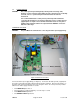
Turn the mains supply off.
Using the short lead supplied, connect the positive terminal of one battery to the negative terminal of
the other battery. Connect the red battery lead to the free + battery terminal. Turn the mains on and
connect the black battery lead to the free - battery terminal. After a few seconds, with the batteries
connected, ALL lights should be off with the exception of the POWER ON light. If any faults or
abnormal conditions are indicated, investigate and rectify before connecting the external wiring.
CONNECTING EXTERNAL WIRING
If the panel has powered-up correctly, SWITCH OFF the mains and DISCONNECT one of the battery
leads and then connect the external field wiring as follows:
Remove the 10µF end of line capacitor from the zone terminals. Connect the external zone wiring
(observing correct polarity) and fit the EOL capacitor to the last device on the zone.
Remove the 6K8 end of line resistor from the alarm circuit terminals. Connect the external sounder
wiring (observing correct polarity) and fit the EOL resistor to the last device on the sounder circuit.
CAUTION The Sounders must be polarized and suppressed. DO NOT exceed the total
alarm load (see Technical Data).
Remove the 6K8 end of line resistor from the fire output terminals. Connect the external fire output
wiring (observing correct polarity) and fit the EOL resistor to the last device on the fire output circuit.
TESTING
When all panel circuits have been connected, switch on the mains supply and then connect the
disconnected battery lead. Rectify any faults indicated by the control panel. Ensure a fault is shown
when ANY zone, alarm circuit or fire output circuit is open or short-circuited, or when a detector is
removed from its base. Check that all detectors and manual call points raise an alarm, all auxiliary
fire alarm devices are operating correctly and all fire output devices are operating correctly.
NOTE To silence and reset the system after a panel alarm condition has been raised, Panel
Access must be enabled. Check that manual call points still raise an alarm condition when
any detector head is removed from the same zone.
Switch off the mains supply:
• The POWER ON light flashes
• The panel buzzer sounds intermittently 1 second every 10 seconds
• The POWER FAULT light flashes
• The GENERAL FAULT light flashes
Turn on the mains. All lights should be off with the exception of the POWER ON light.
ACCESS LEVEL 3 (ENGINEER MODE) is indicated by the ACCESS light flashing 1 second on, 1
second off. When in engineer mode all panel engineer functions can be accessed and this allows the
engineer to enter several panel functions for panel configuration and test. To enter engineer mode, in
Access Level 2:
• Press MENU switch
• Press switch 2
• Enter the engineer code 7134
• Press switch 2 and select function
To exit engineer mode at any time press the EXIT switch, or do not operate any other switch for 30
seconds.