
User's Manual

TM0110 Page 15 of 22 Issue 1.00
3.4 COMMISSIONING
CAUTION The control panel may be damaged by removing and/or inserting cards,
modules, or interconnecting cables while the unit is energised. Do not attempt
to install, service or operate this panel until this manual is read and
understood.
It is recommended that the control panel is powered-up and tested before
connecting the field devices as follows: Temporarily connect a 10µF capacitor
(supplied) into each pair of zone terminals and a 6K8 resistor to each pair of
auxiliary alarm terminals and the fire output terminals. DO NOT connect the
batteries at this stage.
POWERING THE PANEL
WARNING The panel MUST be earthed before connecting the mains input supply wiring.
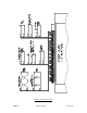
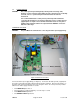
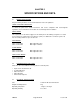
Figure 5: Electrical Connections
Connect the mains input supply wiring (see Figure 5). Connect the two battery leads (supplied) into
the positive (red lead) and negative (black lead) panel battery terminals. Place the two batteries on
the lower shelf of the panel back box and secure using the “Velcro” hook & loop fastener provided.
Switch on the mains supply and wait 10 seconds:
• The POWER ON light comes on
• The panel buzzer sounds intermittently 1 second every 3 seconds
• The POWER FAULT light flashes
• The GENERAL FAULT light flashes
Battery Terminals
PSU Fault Output
Mains Input L ¦ E ¦ N
24V Output to Mother Board
Battery
Temperature
Monitoring