
User's Manual

TM0110 Page 13 of 22 Issue 1.00
polarised. Non-polarised sounders will show a sounder fault. The most common sounders are bells
and electronic sounders. The same type of sounder must be used throughout the building and it must
be distinctive so that the sound associated with a fire alarm is easily recognised. The voltage drop on
each alarm circuit should be calculated to ensure that the minimum voltage at the end of each circuit
exceeds the minimum required by each sounding device. The voltage at the end of the circuit is
calculated by:
Minimum alarm voltage = 21V - (Alarm current in Amps x 2 x alarm circuit length in metres x cable
resistance per core per metre).
Typical resistance per metre values are:
1.5 sq mm - 15m ohms per metre per core.
2.5 sq mm - 9m ohms per metre per core.
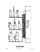
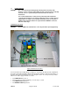
The alarm circuit terminals are labelled ALARM 1, + -, ALARM 2, + -.
ZONE CIRCUITS
The panel provides 2, 4 or 8 conventional zones of detection. Each zone circuit MUST be terminated
with a 10µF capacitor. No active end of line terminator is required as detector head removal
monitoring circuitry is built into the panel. A maximum of 32 smoke/heat detectors can be fitted on
each zone circuit and there is no limit to the number of manual call points which can be used.
Detector bases with integral continuity diodes must be used to ensure manual call points remain
operational when a detector head is removed from its base. Manual call points with integral resistors
must be used to prevent a short circuit fault occurring instead of a fire condition when activated. The
zone circuits are current limited and overload protected by power resistors, which will allow a
maximum of 80 mA 24V to be drawn by each circuit. The zone circuit terminals are labelled ZONE 1 -
8,
+
I
-
NOTE To comply with the requirements of EN54-2, the following conditions must be met:
• The total number of devices on a loop must not exceed 32.
• If output delays are enabled, manual call points should be connected to a
different zone from the fire detectors.
• If coincidence detection is enabled, manual call points should be
connected to a different zone from the fire detectors on the coincidence
zones.
REPEATER CIRCUIT
Up to 7 active repeaters and 7 passive repeaters can be interfaced to the panel over a maximum of
500 metres. The repeaters will mimic panel indications and user switches. Power to the repeater
electronics can be derived from the panel auxiliary 28V supply or from an external power supply.
Connection to and from repeater/s requires 2 core screened cable. The repeater terminals are
labelled A, B and SCREEN. If the panel is to supply power to the repeater(s) then a 4 core screened
cable is required. Terminations are labelled A, B, SCREEN, +28V and 0V (AUX 28V). If a repeater is
to be connected to the panel, link LK3 needs to be made. This option is not available in the 2 zone
version.
INPUT/OUTPUT OPTION CARDS
Input/output peripheral boards (refer to the appropriate data sheet) can be connected internally to the
panel or externally over a maximum of 500 metres. Power to the input/output electronics can be
derived from the panel auxiliary 28V supply or from an external power supply. Connection to and
from input/output peripheral boards requires 2 core screened cable. Input/output card terminals are
labelled IP/OP A, B. If the panel is to supply power to the input/output boards then 4 core screened
cable is required. Terminations are labelled A, B, SCREEN, +28V and 0V (AUX 28V).