
User's Manual

TM0110 Page 12 of 22 Issue 1.00
last device in each of the zone wirings, end of line resistors across auxiliary alarm circuits and fire
outputs. Connect all field devices. Once any field bases or devices are connected, DO NOT USE a
high voltage Megger on the circuitry; low voltage multimeters may be used. Verify using a multimeter
that all zone, auxiliary alarm circuit and fire output end of line capacitors and resistors can be seen. If
a zone, auxiliary alarm circuit or the fire output is not used, then the appropriate end of line capacitor
or resistor MUST be fitted in the panel field terminals.
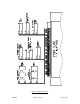
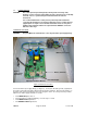
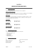
3.3 CIRCUIT CONNECTION DETAILS
The panel provides field wiring connections (see Figure 4) whose functions are described below:
AUXILIARY 28V SUPPLY
The panel provides an auxiliary 28V DC supply output rated at 500 mA 28V, which may vary during a
mains failed condition. This output is fused and fuse failure will be indicated as a panel fault. The
panel will monitor this output for excessive current drain or for a ruptured fuse and will indicate a
panel fault if one of the above conditions occurs. This supply allows for external peripherals to be
powered from the panel. The auxiliary supply terminals are labelled AUX 28V, 28V and 0V.
FIRE OUTPUT [FIRE 1]
The panels provide a fire output rated at 500 mA 28V, which may vary during a mains failed condition.
This output is current limited and overload protected by a smart FET circuit. The output is reverse
polarity monitored for open and short circuit fault conditions. This output MUST be terminated with a
6K8 end of line resistor. When active by any zone fire alarm condition, it will provide 28V DC. Fire
output 1 terminals are labelled FIRE 1, + -. This option is not available in the two zone version.
AUXILIARY FIRE OUTPUT [FIRE 2]
CAUTION This fire output should not be used for any mandatory functions specified by
EN54-2. The volt free relay contacts must not be used to directly switch any
voltage which exceeds 30V DC.
Changeover contacts are provided which operate on any zone fire alarm condition. Fire output 2
terminals are labelled FIRE 2, NO, P, NC.
AUXILIARY FAULT OUTPUT
CAUTION This fault output should not be used for any mandatory functions specified by
EN54-2. The volt free relay contacts must not be used to directly switch any
voltage which exceeds 30V DC.
Changeover contacts are provided which operate on any panel fault condition. This output is fail-safe
and is active in a system fault, or if the system suffers failure of all power supplies. The fault output Is
labelled FAULT, NO, P, NC.
CLASS CHANGE
The panel provides a monitored class change input which, when active, will operate all panel alarm
devices only. When this input is not active the alarm devices will turn off, providing there are no
standing alarm conditions. To use the input, a normally open switch contact needs to be connected
aross the terminals labelled CLASS, + -.
ALARM CIRCUITS
The panel provides 2 alarm circuits, each rated at 500 mA 28V, which may vary during a mains failed
condition. The alarm circuits are current limited and overload protected by smart FET circuits. The
alarm circuits are reverse polarity monitored for short circuit and open circuit fault conditions. The
alarm circuits MUST be terminated with a 6K8 end of line resistor. All devices fitted must be