
User's Manual

A UTC Fire & Security Company
400 Main Street
Ashland, MA 01721
Ph: 508.881.2000
Fax: 508.881.8920
www.kiddefiresystems.com
This literature is provided for informational purposes only. KIDDE-FENWAL, INC.
assumes no responsibility for the product’s suitability for a particular application. The
product must be properly applied to work correctly.
If you need more information on this product, or if you have a particular problem or ques-
tion, contact KIDDE-FENWAL, INC., Ashland, MA 01721. Telephone: (508) 881-2000.
K-90-103 Rev AB © 2007 Kidde-Fenwal Inc. Printed in USA
5. Apply thread tape to the NPT male thread of the
second 1/8-in. x 1/4-in. flared fitting and thread into
one side of the 1/8-in. branch tee. Tighten the flared
fitting.
6. Apply thread tape to the male end of the Schrader
valve. Securely threading the male end into the
open end of the 1/8-in. branch tee. Apply Schrader
cap to Schrader fitting.
7. Connect 1/4-in. actuation hose to flare fitting that
was applied to the 1/8-in. branch tee.
8. Connect the other end of the 1/4-in. actuation hose
into the flare fitting that was connected in the busing
in Step 3.
9. Remove the protection cap from the cylinder valve.
10. Using a suitable wrench, assemble control head to
cylinder valve and tighten swivel nut securely.
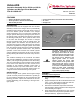
Figure 1. Actuation Kit Assembly
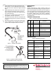
Figure 2. Cylinder and Valve Assembly
with Assembled Actuation Components
MAINTENANCE
MONTHLY:
Inspect components for cracks, corrosion, grime, etc.
Ensure that the assembled fittings are tightly secured at
each of their respective connections and to the agent cyl-
inder. If any defects are found during the monthly inspec-
tion, immediately contact a Kidde Distributor to service
the systems. Please refer to the Design, Installation,
Operation and Maintenance Manual for more details (P/N
90-FM200M-030).
ORDERING INFORMATION
SPECIFICATIONS
1. FITTING–NITROGEN TRANSFER
2. VALVE–PNEUMATIC ACTUATOR
3. FITTING–FLARED 1/8" x 1/4”
4. HOSE–FLEXIBLE 3/16”
5. TEE–1/8" BRANCH
6. VALVE–SCHRADER
7. CAP–SCHRADER VALVE
2
4
3
5
6
7
1
3
CONNECT TO NITROGEN DRIVER
USING P/N 06-118207-00X
FOR NITROGEN MANIFOLD SYSTEMS,
USE HOSE P/N 06-118324-001*
*NOTE: TO CONNECT INTO
PIPING MANIFOLD, REFER TO THE DESIGN,
INSTALLATION, OPERATION AND
MAINTENANCE MANUAL, P/N 90-FM200M-030.
Table 1: Actuation Assembly Kit Part Numbers
Item
No.
Qty. Part Number Description
1 1 06-236124-001 NitrogenTransfer Fitting
2 1 878737 Pressure Operated Control
Head
3 2 06-118191-001 Fitting flared 1/8-in. x 1/4-in.
4 1 06-118193-001 3/16-in. Flexible Actuation
Hose, 16-in. length
5 1 06-118192-001 1/8-in. Branch Tee
6 1 WK-263303-000 1/8-in. Schrader Valve
7 1 WK-263304-000 1/8-in. Schrader Valve Cap
Table 2: Materials Specifications
Part Number Description Material
06-236124-001 Nitrogen Transfer Fitting Brass
06-118191-001 1/8-in. x 1/4-in.
Flared Fittings
Brass
06-118193-001 3/16-in. Flexible
Actuation Hose
Stainless Steel
Braiding, Brass
Fittings
06-118192-001 1/8-in. Branch Tee Brass
WK-263303-000 1/8-in. Schrader Valve Brass
WK-263304-000 1/8-in. Schrader Valve
Cap
Brass
878737 Pressure Operated
Control Head
Brass