
User's Manual

A UTC Fire & Security Company
Effective: April 2007
K-90-103
Kidde ADS
Actuation Assembly Kit for 225-lb and 395-lb.
Cylinders and Nitrogen Driver Manifolds
P/N: 06-129882-001
FEATURES
• Reduces the Number of Control Heads
• Allows Cylinders to Actuate Simultaneously
• Safe and Easy to Install
• Pressure Relief Device Included for Safe Disassembly
• UL Listed
• FM Approved
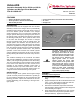
DESCRIPTION
Each Kidde ADS must be equipped with the actuation
assembly in order for the nitrogen driver to pneumatically
actuate the agent cylinder. The nitrogen driver is set up to
act as the master cylinder. Actuation of the nitrogen
driver is initiated by use of a control head; it initiates the
nitrogen system discharge by opening the pilot check on
the cylinder valves. This allows the nitrogen to pressurize
the discharge head piston, which opens the main check
in the valve and discharges the contents of nitrogen
through the transfer hose. From the transfer hose, the
nitrogen splits in two directions. The first path the nitro-
gen takes is through the orifice fitting were the nitrogen
pressure is regulated into the agent cylinder. At the same
time, the nitrogen travels through the actuation assembly
to the pressure operated control head. The pressure
operated control head actuates the FM-200 cylinder
valve by releasing the pressure off the top of the piston,
thereby allowing the FM-200 to be driven out by the nitro-
gen.
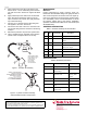
The actuation assembly kit for the 225-lb. and 395-lb.
ADS (P/N 06-129882-001) consists of seven parts (see
Table 1). The nitrogen fitting threads into the orifice fitting.
The 1/8-in. flare allows for the connection of the actuation
hose, which is then fitted into the 1/8-in. branch tee for
operation of the pressure operated control head. A
Schrader valve and cap is then added to the 1/8-in. tee
as a safety for venting off residual pressure after dis-
charge and before decommissioning of the system.
INSTALLATION
Once the nitrogen driver cylinder and the agent storage
cylinder are safely secured and attached to system pip-
ing, the actuation assembly can be connected using the
following procedure. Inspect and assemble the kit com-
ponents separately, prior to attaching to the agent stor-
age cylinder.
ASSEMBLY:
Assembly of Kit Components
1. Apply thread tape to male thread of nitrogen transfer
fitting.
2. Apply thread tape to the NPT male thread of the first
1/8-in. x 1/4-in. flared fitting, thread NPT male into
the nitrogen transfer fitting and tighten.
3. Take the two assembled components and thread
into orifice fitting already attached to the nitrogen dif-
fuser assembly, then tighten.
4. Apply thread tape to the male end of 1/8-in. branch
tee and thread into the pressure operated control
head (P/N 878737). Tighten the branch tee.
WARNING
The agent storage cylinder must be
permanently connected into the sys-
tem piping. Never attach the control
head to the cylinder valve until the cyl-
inders are secured in brackets or rack-
ing and the hose is attached to the
agent cylinder. Under no circum-
stances should the control head
remain attached to the cylinder valve
after removal from service or during
shipment, handling, storage or filling.
In the event of inadvertent discharge,
failure to follow these instructions
could result in death, serious bodily
injury and/or property damage.