
Owner's Manual

Tuning and Controls
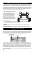
Your Powered Substation accepts either low (line) levels input from the RCA outputs
on your head unit or high (speaker) level input from your system’s speaker wiring. The
diagrams below illustrate both wiring schemes.
DO NOT USE THE LOW LEVEL AND HIGH
LEVEL INPUTS AT THE SAME TIME THIS COULD DAMAGE YOUR UNIT.
TURN ON MODE: *
LOW LEVEL RCA INPUT
BROWN
RED
ORANGE
REMOTE +12V (OPTIONAL)
10 GA.
FUSE
BLACK
GROUND
BATTERY+
OUTPUT TO REMOTE SUBSTATION
(OPTIONAL)*
–
+
YELLOW
* SET TO "REMOTE" IF CONNECTING REMOTE TURN-ON WIRE
SET TO "AUTO" IF REMOTE TURN-ON WIRE IS NOT CONNECTED
–
BLUE/BLACK
+
BLUE
–
WHITE/BLACK
+
WHITE
+
–
–
+
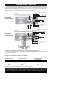
FACTORY SPEAKER WIRING
RED
10 GA.
FUSE
BLACK
GROUND
BATTERY+
TURN ON MODE: *
REMOTE +12V (OPTIONAL)
* SET TO "AUTO" IF REMOTE TURN-ON WIRE IS NOT CONNECTED
SET TO "REMOTE" IF CONNECTING REMOTE TURN-ON WIRE
ORANGE
BROWN
OUTPUT TO REMOTE SUBSTATION
(OPTIONAL)*
–
+
YELLOW
Low-Level
Input Wiring
High-Level
Input Wiring
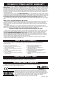
*Adding an additional Substation to your Powered Substation
Your PS80 or PS60 can drive a matching unpowered Substation (see diagrams above
for wiring instructions).
Components MUST be matched as follows:
Powered Model Remote Model Remote Model
Impedance
PS80 KS80 4Ω
PS60 KS60 8Ω
The PSR100 is not designed to drive remote Substations!
If you have more questions about the installation of your new KICKER component, see
the Authorized KICKER Dealer where you purchased your component. You may also call
our Technical SERVICES Line at 405-624-8583 or contact us via email at www.kicker.com.
3