
Installation Sheet
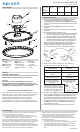
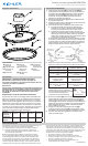
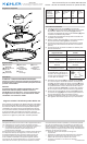
Table Of Contents

We’re here to help 866-558-5706
Hrs: M-F 9am to 5pm EST
IS-44248LED-US
This device complies with part 15 of the FCC Rules. Operaon is
subject to the following two condions:
1) This device may not cause harmful interference, and
2) This device must accept any interference received, including
interference that may cause undesired operaon.
Note: This equipment has been tested and found to comply with
the limits for a Class B digital device, pursuant to part 15 of the FCC
Rules. These limits are designed to provide reasonable protecon
against harmful interference in a residenal installaon. This
equipment generates, uses and can radiate radio frequency energy
and, if not installed and used in accordance with the instrucons,
may cause harmful interference to radio communicaons.
However, there is no guarantee that interference will not occur
in a parcular installaon. If this equipment does cause harmful
interference to radio or television recepon, which can be
determined by turning the equipment o and on, the user is
encouraged to try to correct the interference by one or more of
the following measures:
• Reorient or relocate the receiving antenna.
• Increase the separaon between the equipment and receiver.
• Connect the equipment into an outlet on a circuit dierent
from that to which the receiver is connected.
• Consult the dealer or an experienced radio/TV technician for
help.
FCC Informaon:
Juncon
Box Shape
and
Diameter
4”
Square
4”
Octagonal
3”
Round*
4”
Round
Minimum
Depth
1-1/2” 2-1/8” 3” 2-1/4”
Installaon Instrucons
1) Install mounng plate[A] to outlet box[B] (not provided)
with correct side towards outlet box using mounng
screws[C]. Ensure installaon bracket tabs[F] are inside the
juncon box. Mounng plate can be adjusted to suit posion
of xture.
2) Remove decorave ring[I] by gently twisng it counter-
clockwise.
3) Connect xture ground to outlet box ground using supplied
connector.
4) Grounding instrucons: (See Illus. a or b).
a) On xtures where mounng strap is provided with a hole
and two raised dimples, wrap ground wire from outlet
box around green ground screw, and thread into hole.
b) On xtures where a cupped washer is provided, aach
ground wire from outlet box under cupped washer and
green ground screw then thread into mounng strap.
If xture is provided with ground wire. Connect xture
ground wire to outlet box ground wire with wire connector
(Not provided) aer following the above steps. Never
connect ground wire to black or white power supply wires.
5) Make wire connecons. Reference chart below for
correct connecons and wire accordingly.
Connect Black or Red
Supply Wire to:
Connect White Supply
Wire to:
Black White
*Parallel cord (round &
smooth)
*Parallel cord (square &
ridged)
Clear, Brown, Gold or
Black without Tracer
Clear, Brown, Gold or Black
with Tracer
Insulated wire (other
than green) with copper
conductor
Insulated wire (other
than green) with silver
conductor
*Note: When parallel wire (SPT
1 & SPT 2) are used. The neutral
wire is square shaped or ridged
and the other wire will be round
in shape or smooth (See illus.)
Neutral Wire
6) Posion the xture[D] over the outlet box[B] making sure
the center of the xture is centered over the outlet box. Align
spring clips[E] and tabs[F] in mounng bracket and insert
unl spring clips pull the xture to ceiling surface. NOTE: Be
certain wires do not get pinched between xture and ceiling.
7) Push the drywall anchor screws[H] through the anchor
holes[G] in the xture then screw them into the ceiling to
secure the xture in place.
8) Install decorave ring by twisng clockwise unl secure.
GREEN GROUND
SCREW
CUPPED
WASHER
OUTLET BOX
GROUND
FIXTURE
GROUND
DIMPLES
WIRE CONNECTOR
OUTLET BOX
GROUND
GREEN GROUND
SCREW
FIXTURE
GROUND
a
b
CAUTION – RISK OF SHOCK –
Disconnect Power at the main circuit breaker panel or main
fusebox before starng and during the installaon.
Warning:
This xture is intended for installaon in accordance
with the Naonal Electrical Code (NEC) and all local code
specicaons. If you are not familiar with code requirements,
installaon by a cered electrician is recommended.
Fixture Diagram
Parts List
[A] Mounting
Plate
[B] Outlet Box
[C] Mounting
Screws
[D] Fixture
[E] Spring Clips
[F] Installation
Bracket Tabs
[G] Anchor Holes
[H] Drywall
Anchors
Screws
[I] Decorative
Ring
Cauons
Kichler Zeo Juncon Box Requirements
To comply with the Naonal Electric Code (NEC), Kichler Zeo
light xtures require a juncon box with a minimum internal
volume of 18 cubic inches (in3) for installaon (internal
volume is typically called out on the inside panel).
The juncon boxes listed below meet the minimum
requirements. Be sure to select a size and shape that has a
depth greater than or equal to the specied minimum depth.
B
C
A
F
G
E
H
D
I