
Installation Sheet
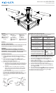
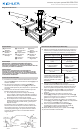
Table Of Contents

IS-44224-US
We’re here to help 866-558-5706
Hrs: M-F 9am to 5pm EST
4) Make wire connecons. Reference chart below for
correct connecons and wire accordingly.
Connect Black or Red
Supply Wire to:
Connect White Supply
Wire to:
Black White
*Parallel cord (round &
smooth)
*Parallel cord (square &
ridged)
Clear, Brown, Gold or
Black without Tracer
Clear, Brown, Gold or Black
with Tracer
Insulated wire (other
than green) with copper
conductor
Insulated wire (other
than green) with silver
conductor
*Note: When parallel wire (SPT
1 & SPT 2) are used. The neutral
wire is square shaped or ridged
and the other wire will be round
in shape or smooth (See illus.)
Neutral Wire
5) Push xture[G] to ceiling, carefully passing mounng
screws through holes in canopy. NOTE: Be certain wires
do not get pinched between canopy and ceiling.
6) Use lock-up knobs[K] and lockwashers[L] to secure
canopy. Tighten to secure.
7) Find the wood panels without screw holes[B] and verify
that the wood biscuits[J] are in the ends. If they are not
in place, slide the biscuits in place as shown.
8) Take one of the wood panels with screw holes[F] and,
using the screws[H], install it onto the xture with the
cap nuts[I] as shown.
9) Take assembled wood panels[B] and insert into the slot
on the end of wood panel[F] on both sides of the xture.
10) Repeat step 8 above for the remaining panels[F].
11) Install the recommended bulbs.
Fixture Diagram
Parts List
[A] Mounting
Strap
[B] Wood Panels
[C] Mounting
Screws
[D] Strap
Mounting
Screws
[E] Outlet Box
[F] Wood Panels
[G] Fixture
[H] Screws
[I] Cap Nuts
[J] Wood
Biscuits
[K] Lockup Knobs
[L] Lockwashers
Cauons
CAUTION – RISK OF SHOCK –
Disconnect Power at the main circuit breaker panel or main
fusebox before starng and during the installaon.
WARNING:
This xture is intended for installaon in accordance
with the Naonal Electrical Code (NEC) and all local code
specicaons. If you are not familiar with code requirements,
installaon by a cered electrician is recommended.
Installaon Instrucons
E
C
D
A
G
B
F
H
I
B
F
J
K
L
1) Find the appropriate threaded holes on mounng
strap[A]. Assemble mounng screws[C] into threaded
holes.
2) Aach mounng strap to outlet box[E] using the
strap mounng screws[D]. The mounng strap can be
adjusted to suit posion of xture.
3) Grounding instrucons: (See Illus. a or b).
a) On xtures where mounng strap is provided with a
hole and two raised dimples, wrap ground wire from
outlet box around green ground screw, and thread
into hole.
b) On xtures where a cupped washer is provided,
aach ground wire from outlet box under cupped
washer and green ground screw, then thread into
mounng strap.
If xture is provided with ground wire, connect xture
ground wire to outlet box ground wire with wire
connector (Not provided) aer following the above steps.
Never connect ground wire to black or white power
supply wires.
GREEN GROUND
SCREW
CUPPED
WASHER
OUTLET BOX
GROUND
FIXTURE
GROUND
DIMPLES
WIRE CONNECTOR
OUTLET BOX
GROUND
GREEN GROUND
SCREW
FIXTURE
GROUND
a
b
Installaon Instrucons (connued)