
Instruction Sheet

1) Insert recommended bulb. (Bulb included)
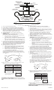
2) To attach diffuser, raise metal plate up towards canopy of fixture.
3) There are four tabs located on arms of fixture body. Tilt diffuser and
place edge of opening of diffuser over tab on one arm of fixture.
4) Fit diffuser over remaining tabs on arms, one tab at a time, by raising
diffuser up towards fixture body and tilting diffuser. Tabs should fit just
inside the opening of diffuser. Diffuser will rest on tabs.
5) Lower metal plate down over top of fixture body and diffuser.
6) TURN OFF POWER.
IMPORTANT: Before you start, NEVER attempt any work without
shutting off the electricity until the work is done.
a) Go to the main fuse, or circuit breaker, box in your home. Place
the main power switch in the “OFF” position.
b) Unscrew the fuse(s), or switch “OFF” the circuit breaker switch(s),
that control the power to the fixture or room that you are working
on.
c) Place the wall switch in the “OFF” position. If the fixture to be
replaced has a switch or pull chain, place those in the “OFF” position.
7) Thread hexnut onto threaded pipe so that approximately 5 threads are
exposed above hexnut. Thread that end of threaded pipe into mounting
strap. Thread second hexnut onto end of threaded pipe protruding from
back of mounting strap. Tighten both hexnuts against mounting strap
8) Attach mounting strap to outlet box. (Screws not provided)
9) Grounding instructions: (See Illus. A or B).
A) On fixtures where mounting strap is provided with a hole and
two raised dimples. Wrap ground wire from outlet box around
green ground screw, and thread into hole.
B) On fixtures where a cupped washer is provided. Attach ground
wire from outlet box under cupped washer and green ground
screw, and thread into mounting strap.
If fixture is provided with ground wire. Connect fixture ground wire
to outlet box ground wire with wire connector. (Not provided.) After
following the above steps. Never connect ground wire to black or white
power supply wires.
10) Make wire connections (connectors not provided.) Reference chart
below for correct connections and wire accordingly.
11) Push fixture to ceiling, carefully passing threaded pipe through hole.
12) Secure fixture to ceiling using finial.
CAUTION: BAllAsT MUsT Be RePlACed By A QUAlIfIed eleCTRI-
CIAN.
GREEN GROUND
SCREW
CUPPED
WASHER
A
B
OUTLET BOX
GROUND
FIXTURE
GROUND
DIMPLES
WIRE CONNECTOR
(NOT PROVIDED)
OUTLET BOX
GROUND
GREEN GROUND
SCREW
FIXTURE
GROUND
Connect Black or
Red Supply Wire to:
Connect
White Supply Wire to:
Black White
*Parallel cord (round & smooth)
*Parallel cord (square & ridged)
Clear, Brown, Gold or Black
without tracer
Clear, Brown, Gold or Black
with tracer
Insulated wire (other than green)
with copper conductor
Insulated wire (other than green)
with silver conductor
*Note: When parallel wires (SPT I & SPT II)
are used. The neutral wire is square shaped
or ridged and the other wire will be round in
shape or smooth (see illus.)
Neutral Wire
Date Issued: 6/11/10 IS-10898-US
MOUNTING STRAP
PLANCHA PARA
MONTAR
FIXTURE
ARTEFACTO
FINIAL
CAPUCHÓN
THREADED PIPE
TUBO ROSCADO
HEXNUT
TUERCA HEXAGONAL
1) Inserte la bombilla recomendada. (Se incluye la bombilla.)
2) Para acoplar el difusor, levante la placa de metal arriba hasta el
escudete del artefacto.
3) Hay cuatro orejetas localizadas en los brazos del cuerpo del artefacto.
Incline el difusor y ponga el borde de la abertura del difusor encima de
la orejeta en uno de los brazos del artefacto.
4) Encaje el difusor encima de las orejetas restantes en los brazos, una
orejeta por vez, levantando el difusor arriba hasta el cuerpo del
artefacto e inclinando el difusor. Las orejetas deben encajar justas
dentro de la abertura del difusor. El difusor descansará en las orejetas.
5) Baje la placa de metal abajo, encima de la parte superior del cuerpo del
artefacto y del difusor.
6) APAGUE LA ALIMENTACIÓN ELÉCTRICA.
IMPORTANTe: Antes de comenzar, NUNCA trate de trabajar sin antes
desconectar la corriente hasta que el trabajo se termine.
a) Vaya a la caja principal de fusibles, o interruptor o caja de circuitos
de su casa. Coloque el interruptor de la corriente principal en
posición de apagado “OFF”.
b) Desatornille el (los) fusible (s), o coloque el interruptor o
interruptores del breaker en posición de apagado “OFF”, que
controla (n) la corriente hacia el artefacto o habitación donde está
trabajando.
c) Coloque el interruptor de pared en posición de apagado “OFF”. Si
el artefacto que se va a reemplazar tiene un interruptor o cadena
que se jala, colóquelos en la posición de apagado “OFF”.
7) Rosque la tuerca hexagonal en el tubo roscado de modo que
aproximadamente 5 roscas estén expuestas arriba de la tuerca hexagonal.
Rosque ese extremo del tubo roscado en la abrazadera de montaje.
Rosque una segunda tuerca hexagonal en el extremo del tubo roscado
que sobresale de atrás de la abrazadera de montaje. Apriete ambas
tuercas hexagonales contra la abrazadera de montaje.
8) Sujete la plancha para montar a la caja de conexión. (No se proveen
los tornillos.)
9) Instrucciones de conexión a tierra solamente para los Estados Unidos.
(Vea la ilustracion A o B).
A) En las lámparas que tienen el fleje, de montaje con un agujero
y dos hoyuelos realzados. Enrollar el alambre a tierra de la caja
tomacorriente alrededor del tornillo verde y pasarlo por el aquiero.
B) En las lámparas con una arandela acopada. Fijar el alambre a
tierra de la caja tomacorriente del ajo de la arandela acoada y
tornillo verde, y paser por el fleje de montaje.
Si la lámpara viene con alambre a tierra. Conecter el alambre a tierra
de la lámpara al alambre a tierra de la caja tomacorriente con
un conector de alambres. (No incluido) Espués de seguir los pasos
anteriores. Nunca conectar el alambra a tierra a los alambres eléctros
negro o blanco.
10) Haga les conexiones de los alambres (no se proveen los connectores.)
La tabla de referencia de abajo indica las conexiones correctas y los
alambres correspondientes.
11) Empuje la unidad contra la pared, pasando con cuidado el tubo roscado
a través del agujero.
12) Sujete la unidad contra la pared apretándola con la capuchón.
PReCAUCIÓN: el esTABIlIzAdOR de TeNsIÓN lO deBe CAMBIAR
UN eleCTRICIsTA IdÓNeO.
GREEN GROUND
SCREW
CUPPED
WASHER
A
B
OUTLET BOX
GROUND
FIXTURE
GROUND
DIMPLES
WIRE CONNECTOR
(NOT PROVIDED)
OUTLET BOX
GROUND
GREEN GROUND
SCREW
FIXTURE
GROUND
Connect Black or
Red Supply Wire to:
Connect
White Supply Wire to:
Black White
*Parallel cord (round & smooth) *Parallel cord (square & ridged)
Clear, Brown, Gold or Black
without tracer
Clear, Brown, Gold or Black
with tracer
Insulated wire (other than green)
with copper conductor
Insulated wire (other than green)
with silver conductor
*Note: When parallel wires (SPT I & SPT II)
are used. The neutral wire is square shaped
or ridged and the other wire will be round in
shape or smooth (see illus.)
Neutral Wire
DIFFUSER
DIFUSOR
ARM
BRAZO
TA B
OREJETA
METAL PLATE
PLACA DE METAL
BULB
BOMBILLA