
User Manual


Table Of Contents
- About this Manual
- Chapter 1: Product Overview
- Chapter 2: Installation
- Chapter 3: Getting Started
- Chapter 4: Using the DVR
- Chapter 5: KGUARD Web Client
- 5.1 Login
- 5.2 The Interface
- 5.3 Live Viewing
- 5.4 Searching and Playing Recorded Videos
- 5.5 Remote Settings
- 5.6 Local Settings
- Chapter 6: Using KView Series Software
- Chapter 7: Troubleshooting & FAQ
- Appendix: Specifications
ENGLISH
Chapter 2: Installaon
DVR User’s Manual
21
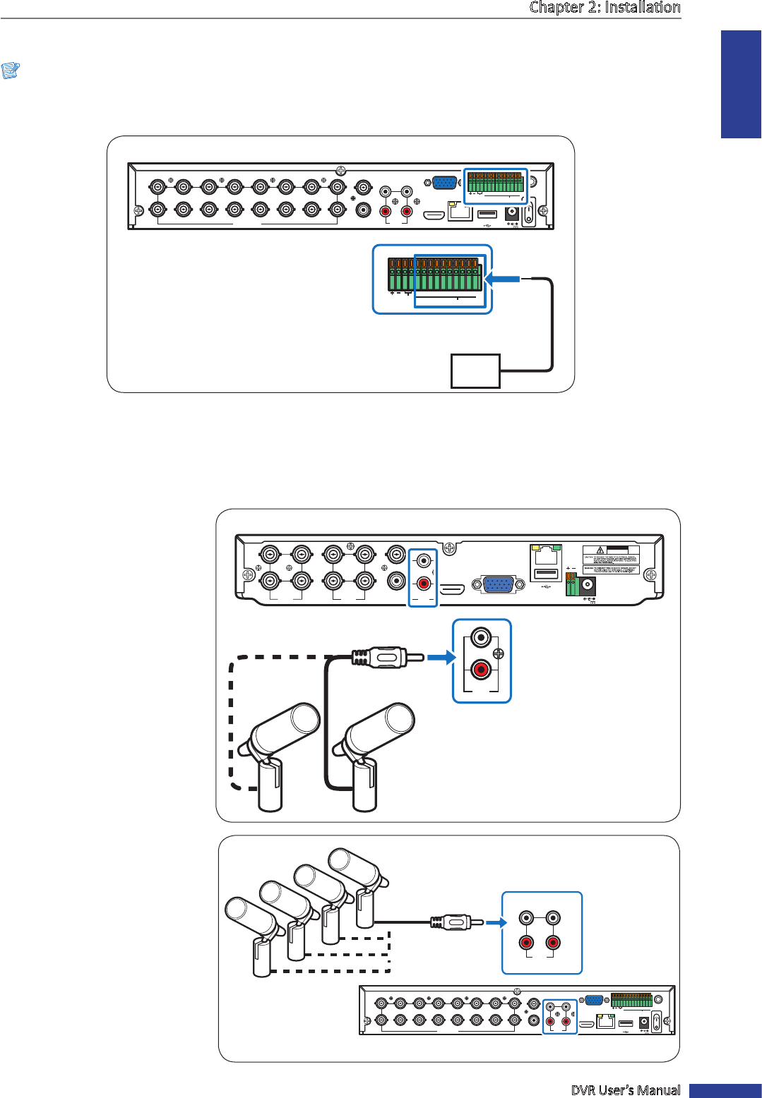
2.6 Connecng the Sensors
Note:
Available in 16-channel DVRs only.
You can connect sensors up to 8 channels. The connectors are labelled according to channels.
RS-485 ALARM
SENSOR
G1234G5678
HDMI
5
6
7
8
1
2
AUDIO
OUTPUT
1
2
3
4
13
14
15
16
9
10
11
12
VIDEO INPUT
3
4
AUDIO
INPUT
VIDEO OUTPUT
LAN
VGA
IR-EXT
12V
RS-485 ALARM
SENSOR
G 1234G5678
Sensor device
(input)
16-Channel DVR
2.7 Connecng the Microphones
The DVR supports up to 4 audio input channels. Microphones can be connected directly via RCA connecon.
VIDEO
INPUT
LAN
RS-485VGA
12V
CAUTION
RISK OF ELECTRIC SHOCK
DO NOT OPEN
HDMI
5
6
7
8
1
2
AUDIO
OUTPUT
1
2
3
4
VIDEO
INPUT
AUDIO
INPUT
VIDEO
OUTPUT
1
2
AUDIO
INPUT
Microphone
RCA audio
cable
4-Channel / 8-Channel DVR
2.7.1 RCA Connecon
Connect the microphone(s) using
RCA cable connecon as shown.
RS-485 ALARM
SENSOR
G1234G5678
HDMI
5
6
7
8
1
2
AUDIO
OUTPUT
1
2
3
4
13
14
15
16
9
10
11
12
VIDEO INPUT
3
4
AUDIO
INPUT
VIDEO OUTPUT
LAN
VGA
IR-EXT
12V
1
2
3
4
AUDIO
INPUT
16-Channel DVR
Microphone
RCA audio cable