MIDEA 60Hz DEHUMIDIFIER K SERIES
CONTENTS 1. Precaution ............................................................................................................................................. 1 1.1 Safety Precaution ............................................................................................................................... 1 1.2 Warning ............................................................................................................................................... 1 2. Display .........
1. Precaution 1.1 Safety Precaution To prevent injury to the user or other people and property damage, the following instructions must be followed. Incorrect operation due to ignoring instruction will cause harm or damage. Before service unit, be sure to read this service manual at first. 1.2 Warning Installation Do not use a defective or underrated circuit breaker. Use this appliance on a dedicated circuit. There is risk of fire or electric shock.
Do not install the product on a defective installation stand. It may cause injury, accident, or damage to the product. Be sure the installation area does not deteriorate with age. If the base collapses, the air conditioner could fall with it, causing property damage, product failure, and personal injury. Do not let the air conditioner run for a long time when the humidity is very high and a door or a window is left open. Moisture may condense and wet or damage furniture.
There is risk of property damage, failure of product, or electric shock. Do not open the inlet grill of the product during operation. (Do not touch the electrostatic filter, if the unit is so equipped.) There is risk of physical injury, electric shock, or product failure. When the product is soaked (flooded or submerged), contact an Authorized service center. There is risk of fire or electric shock. Be caution that water could not enter the product.
Operational Do not expose the skin directly to cool air for long periods of time. (Do not sit in the draft). This could harm to your health. Do not use the product for special purposes, such as preserving foods, works of art, etc. It is a consumer air conditioner, not a precision refrigerant system There is risk of damage or loss of property. Do not block the inlet or outlet of air flow. It may cause product failure. Use a soft cloth to clean. Do not use harsh detergents, solvents, etc.
2. Display CAN-CFZ0.6BD/N1-K(A9)(MDK-30AEN1-BA9), CAN-CFZ0.6BD/N1-K(A9)-[J](MDK-30AEN1-BA9) CAN-CFZ0.8BD/N1-K(A9)(MDK-40AEN1-BA9), CAN-CFZ1.0BD/N1-K(A9)(MDK-50AEN1-BA9) CAN-CFZ1.0BD/N1-K(A9)-[J](MDK-50AEN1-BA9), CAN-CFZ1.2BD/N1-K(A9)-[J](MDK-60AEN1-BA9) CAN-CFZ1.4BD/N1-K(A9)-[J](MDK-70AEN1-BA9), CAN-CFZ1.2BD/N1-K(A9)(MDK-60AEN1-BA9) CAN-CFZ1.
CAN-CFZ1.0BD/N1-K(A9)-B(MDK-50AEN1-BA9B) CAN-CFZ1.4BD/N1-K(A9)-B(MDK-70AEN1-BA9B) With water pump Continue pad: Press to activate the continuous dehumidifying operation Filter pad The check filter feature is a reminder to clean the Air Filter for more efficient operation. The Filter light(Clean filter l ight) will illuminate after 250 hours of operation. To reset after cleaning the filter, press the Filter pad and the light will go off. Fan pad Control the fan speed.
Power pad Press to turn the dehumidifier on and off. Humidity set control pad(down and up) The humidity level can be set within a range of 35%RH(Relative Humidity) to 85%RH(Relative Humidity) in 5% increments.For drier air, press the For damper air, press the pad and set to a lower percent value(%). pad and set a higher percent value(%).
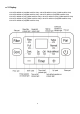
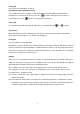
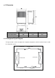
3. Dimension Dimension Mode W(mm) H(mm) D(mm) 25Pint,30Pint,40Pint 360 510 251 50Pint,60Pint,70Pint 391 590 275 4. Refrigerant Cycle Diagram The figure below is a brief description of the important components and their function in what is called the refrigeration system.
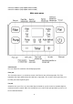
5. Wiring Diagram CAN-CFZ0.6BD/N1-K(A9)(MDK-30AEN1-BA9), CAN-CFZ0.6BD/N1-K(A9)-[J](MDK-30AEN1-BA9) CAN-CFZ0.8BD/N1-K(A9)(MDK-40AEN1-BA9), CAN-CFZ1.0BD/N1-K(A9)(MDK-50AEN1-BA9) CAN-CFZ1.0BD/N1-K(A9)-[J](MDK-50AEN1-BA9), CAN-CFZ1.2BD/N1-K(A9)-[J](MDK-60AEN1-BA9) CAN-CFZ1.4BD/N1-K(A9)-[J](MDK-70AEN1-BA9), CAN-CFZ1.2BD/N1-K(A9)(MDK-60AEN1-BA9) CAN-CFZ1.
CAN-CFZ1.0BD/N1-K(A9)-B(MDK-50AEN1-BA9B) CAN-CFZ1.
6. Features ※ LED display ※ Water pump function(for some models with water pump) ※ Continuous dehumidification mode ※ Water full protection ※ Timer function ※ Check filter function ※ Auto defrost, Anti-freezing control ※ Turbo key function and normal key function ※ Self-diagnosis and auto-protection function. ※ Wait 3 minutes before resuming operation ※ Auto-restart, When the power supply is interrupted and then restore, the unit automatically restore the previous function setting. 7 .
(2) Water full protection (P2) There is one water level switch on the top of water tank. (a) At running status, if the water level of water exceeds the safety water level and the water level switch closed, the unit will protect by itself. It will shut-down all of load and back to work provided the water tank is empty by manual. (b) At wake status, if the water level of water exceeds the safety water level and the water level switch closed, the unit will protect by itself.
When Ha
8 Basic test procedure 8.1 Defective compressor Compressors are single phase, 115V, depending on the model unit. All compressor motors are permanent split capacitor type using only a running capacitor across the start and run terminal. All compressors are internally spring mounted and externally mounted on rubber isolators. 8.1.1 Compressor wiring test Remove compressor terminal box cover and disconnect wires from terminals.
1. Install a piercing valve on the suction and discharge or liquid process tube. 2. Attach gauges to the high and low sides of the system. 3. Start the system and run a “cooling or heating performance test.” If test shows: A. Below normal high side pressure. B. Above normal low side pressure. C. Low temperature difference across coil. The compressor valves are faulty - replace the compressor 8.1.
1. No power to unit, remove the leads from the compressor terminals. 2. Using an ohmmeter, test continuity between terminals C-S and C-R. If not continuous, the compressor overload is open and the compressor must be replaced. 8.2 Sealed refrigeration system repairs 8.2.1 Equipment require 1. Voltmeter 2. Ammeter 3. Ohmmeter 4. E.P.A. Approved Refrigerant Recovery System. 5. Vacuum Pump (capable of 200 microns or less vacuum.) 6. Acetylene Welder 7. Electronic Halogen Leak Detector (G.E.
system to at least 5%. 2. Cut the process tube below pinch off on the suction side of the compressor. 3. Connect the line from the nitrogen tank to the suction process tube. 4. Drift dry nitrogen through the system and unsolder the more distant connection first. (Filter drier, high side process tube, etc.) 5. Replace inoperative component, and always install a new filter drier. Drift dry nitrogen through the system when making these connections. 6.
8.2.5 Rotary compressor special troubleshooting and service Basically, troubleshooting and servicing rotary compressors is the same as on the reciprocating compressor with only a few exceptions. 1. Because of the spinning motion of the rotary, the mounts are critical. If vibration is present, check the mounts carefully. 2. The electrical terminals on the rotary are in a different order than the reciprocating compressors. The terminal markings are on the cover gasket.
8.4 Capacitor A run capacitor is wired across the auxiliary and main winding of a single phase permanent split capacitor motor such as the compressor. A single capacitor can be used for each motor or a dual rated capacitor can be used for both. The capacitor's primary function is to reduce the line current while greatly improving the torque characteristics of a motor. The capacitor also reduces the line current to the motor by improving the power factor of the load.
9 Characteristic of temperature sensor Temp.℃ Temp.℉ Resistance KΩ Temp.℃ Temp.℉ Resistance KΩ Temp.℃ Temp.℉ Resistance KΩ -10 14 62.2756 17 62.6 14.6181 44 111.2 4.3874 -9 15.8 58.7079 18 64.4 13.918 45 113 4.2126 -8 17.6 56.3694 19 66.2 13.2631 46 114.8 4.0459 -7 19.4 52.2438 20 68 12.6431 47 116.6 3.8867 -6 21.2 49.3161 21 69.8 12.0561 48 118.4 3.7348 -5 23 46.5725 22 71.6 11.5 49 120.2 3.5896 -4 24.8 44 23 73.4 10.9731 50 122 3.
10 Troubleshooting In general, possible trouble is classified in three kinds. One is called Starting Failure which is caused from an electrical defect, another is ineffective Air Conditioning caused by a defect in the refrigeration circuit and improper application, and the other is called the Structure Damage. Problem What to check Unit does not start ●Make sure the dehumidifier s plug is pushed completely into the outlet. ●Check the house fuse/circuit breaker box.
DK_1403_B(60Hz,R134a,R410a) 22