
Datasheet


Page 04
Find us at www.keysight.com
U1731C/U1732C/U1733C Electrical Specications
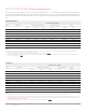
Accuracy is given as ± (% of reading + counts of least significant digit) at 23 °C ± 5 °C, with relative humidity less than 80%. Please re-
fer to the User Guide about the measuring mode specified for each range of L/C/R, series or parallel mode. Measurements performed
at the test socket and necessary Open and Short corrections must prior be done. The accuracy is verified by design and specified type
tests.
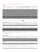
Impedance/Resistance
Accuracy = AZ + Offset
Range Resolution U1731C/U1732C/U1733C U1732C/U1733C U1733C
100 Hz 120 Hz 1 kHz 10 kHz 100 kHz DCR
1
2 Ω
1
0.0001 Ω 0.7% + 50 0.7% + 50 0.7% + 50 0.7% + 50 1.0% + 50 0.7% + 50
20 Ω
1
0.001 Ω 0.7% + 8 0.7% + 8 0.7% + 8 0.7% + 8 0.7% + 8 0.7% + 8
200 Ω
1
0.01 Ω 0.2% + 3 0.2% + 3 0.2% + 3 0.2% + 3 0.5% + 5 0.2% + 3
2000 Ω 0.1 Ω 0.2% + 3 0.2% + 3 0.2% + 3 0.2% + 3 0.5% + 5 0.2% + 3
20 kΩ 0.001 kΩ 0.2% + 3 0.2% + 3 0.2% + 3 0.2% + 3 0.5% + 5 0.2% + 3
200 kΩ 0.01 kΩ 0.5% + 5 0.5% + 5 0.5% + 5 0.5% + 5 0.7% + 8 0.5% + 5
2000 kΩ 0.1 kΩ 0.5% + 5 0.5% + 5 0.5% + 5 0.7% + 5 NA 0.5% + 5
20 MΩ 0.001 MΩ 2.0% + 8 2.0% + 8 2.0% + 8 5.0% + 8 NA 2.0% + 8
200 MΩ 0.01 MΩ 6.0% + 80 6.0% + 80 6.0% + 80 NA NA 6.0% + 80
Notes:
1. The accuracy for ranges 2 Ω to 200 Ω is specified after Null function which is used to subtract the resistance of test leads and the contact resistance
2. For ranges of 20 MΩ and 200 MΩ, the R.H is specified for < 60%
3. Resistance is specified to Q < 10 and D > 0.1, otherwise the accuracy is (AZ+Offset) x √
(1+Q
2
)
4. Equivalence Series Resistance (ESR) measurement is determined by impedance measurement and range. The maximum display is up to 199.99 kΩ and
accuracy is (AZ+Offset) x √
(1+Q
2
)
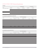
Capacitance
3
Accuracy = AC + Offset
Range Resolution U1731C/U1732C/U1733C U1732C/U1733C U1733C
100 Hz 120 Hz 1 kHz 10 kHz 100 kHz
20 mF 0.001 mF 0.5% + 8 0.5% + 8 NA NA NA
2000 μF 0.1 μF 0.5% + 5 0.5% + 5 0.5% + 8 NA NA
200 μF 0.01 μF 0.3% + 3 0.3% + 3 0.5% + 5 0.5% + 8 NA
20 μF 0.001 μF 0.2% + 3 0.2% + 3 0.2% + 3 0.5% + 5 5.0% + 10
2000 nF 0.1 nF 0.2% + 3 0.2% + 3 0.2% + 3 0.2% + 3 0.7% + 10
200 nF 0.01 nF 0.2% + 3 0.2% + 3 0.2% + 3 0.5% + 3 0.7% + 10
20 nF 0.001 nF 0.5% + 5 0.5% + 5 0.2% + 3 0.5% + 3 0.7% + 10
2000 pF
1
0.1 pF 0.5% + 10 0.5% + 10 0.5% + 5 0.5% + 3 2.0% + 10
200 pF
1
0.01 pF NA NA 0.5% + 10 0.8% + 10 2.0% + 10
20 pF
1
0.001 pF NA NA NA 1.0% + 20 2.5% + 10
Notes:
1. The accuracy for ranges 20 pF – 2000 pF is specified after Null function which is used to subtract the stray capacitances of test leads.
2. The accuracy for the ceramic capacitor will be influenced depending on the dielectric constant (K) of the material used to make the ceramic capacitor. For
related influence factors, please refer to the Component dependency factors section in the Impedance Measurement Handbook, download able for free at
http://www.keysight.com/find/lcrmeters
3. Capacitance is specified to Q > 0.1 and D < 10, otherwise the accuracy is (AZ+Offset) x √
(1+D
2
)