
Datasheet


10 | Keysight | U1240 Series Handheld Digital Multimeters - Data Sheet
www.keysight.com/find/handhelddmm
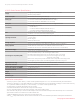
U1240C Series DC Specifications
Function Range Resolution
Accuracy ±(% of reading +
counts of least significant digit) Test current / burden voltage
Voltage
100 mV
1,3
0.01 mV 0.09% + 2 —
600 mV
1,3
0.1 mV 0.09% + 2 —
1000 mV
4
0.1 mV 0.09% + 2 —
10 V
4
0.001 V 0.09% + 2 —
100 V
4
0.01 V 0.09% + 2 —
1000 V
4
0.1 V 0.09% + 2 —
Z
LOW
2,4
(applicable to 1000 V range)
0.1 V 1% + 4 —
Current
5
1000 µA
3
0.1 µA 0.1% + 2 0.032 V (30 Ω)
10 mA
3
0.001 mA 0.1% + 2 0.32 V (30 Ω)
100 mA
1,3
0.01 mA 0.2% + 2 0.2 V (0.5 Ω)
600 mA
1,3
0.1 mA 0.2% + 2 0.88 V (0.5 Ω)
10 A
2,4
0.001 A 0.3% + 5 0.5 V (0.01 Ω)
Diode test — 0.001 V 0.5% + 10 < 1.6 mA
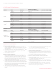
Function Range Resolution
Accuracy ±(% of reading +
counts of least significant digit) Continuity threshold
Resistance /
audible continuity
100 Ω
3,4,7
0.01 Ω 0.2% + 5 28 ±10 Ω
1000 Ω
4
0.1 Ω 0.2% + 2 28 ±10 Ω
10 kΩ 0.001 kΩ 0.2% + 2 0.151 ±0.05 kΩ
100 kΩ 0.01 kΩ 0.2% + 2 1.38 ±0.5 kΩ
1000 kΩ 0.1 kΩ 0.2% + 2 13.8 ±4.3 kΩ
10 MΩ
5
0.001 MΩ 0.8% + 2 0.12 ±0.04 MΩ
100 MΩ
5,6
0.01 MΩ
1.5% + 3 (<50 MΩ)
3.0% + 3 (>50 MΩ)
0.12 ±0.04 MΩ
Notes for DC specifications
A. Notes for voltage specification.
1. 100 mV and 600 mV ranges available on Temperature T1 terminal. The
accuracy is specified for 10 MΩ (nominal) input impedance. The accuracy
is specified after NULL function is used to zero out thermal effect (by
shorting test leads).
2. Only available in U1242C only. 1.8 kΩ typical input impedance for Z
LOW
mode.
3. Overload protection for 100 mV and 600 mV ranges: 1000 Vrms for
circuits < 0.3 A short circuit current.
4. Overload protection: 1000 Vrms.
B. Notes for current specification
1. Current can be measured up to 440 mA continuously. Maximum of 20
hours for measuring current more than 440 mA and up to 600 mA. 100
mA and 600 mA ranges have thermal effect of 0.35 µA/mA to be offset
after current applied to these ranges. Cool down the meter for at least
6 seconds if 100 mA was applied, and at least 3 minutes if 600 mA was
applied; or alternatively use the NULL function to zero-out thermal effect
with open test lead before measuring the signal.
2. Current can be measured up to 10 A continuously. Maximum of 30 sec-
onds for measuring current more than 10 A to 20 A, add 0.3% to specified
accuracy. The multimeter needs to be cool down after measuring current
that is more than 10 A. Cool down the meter for twice the duration of the
measured time and use NULL function to zero-out thermal effect before
proceeding with lower current measurement.
3. 1000 µA to 600 mA ranges (connection with mA terminal) overload
protection by 10 x 35 mm, 440 mA/1000 V, and 10 kA minimum fast-act-
ing fuse.
4. 10 A ranges (connection with A terminal) overload protection by 10 x 38
mm, 11 A / 1000 V, 20 kA minimum fast-acting fuse.
5. Ensure good ventilation and no heat element close to the meter.
C. Notes for diode test specification
1. Overload protection: 1000 Vrms for circuits < 0.3 A short circuit current.
2. Built-in buzzer sounds when reading is below 0.05 V approximately, and
single tone for normal forward-biased diode or semiconductor junction as
0.3 V ≤ reading ≤ 0.8 V.
3. The maximum threshold voltage display is less than +2 V.
D. Notes for resistance/audible Continuity specification
1. Maximum open voltage: < +2.4 V
2. Built-in buzzer sounds as transient when resistance less than 28 ±10 Ω. It
may capture the intermittent for longer than 1 ms.
3. 100 Ω range is for U1242C only
4. The accuracy is specified after Math Null, which is used to subtract the
test lead resistance and the thermal effect. Ensure good ventilation and
no heat element close to the meter.
5. For 10 MΩ and 100 MΩ ranges, the R.H. is specified for < 60% at 30°C.
6. For 100 MΩ range: temperature coefficient is 0.1 x (specified accuracy)
/°C.
7. Resistance range 100 Ω is typical characteristic.