
Datasheet

Page 16
Find us at www.keysight.com
I source overshoot < ±0.1 % (< ±0.3 % for 3 A range). Step is 10 % to 90 % range, resistive load
Current source range change overshoot ≤ 250 mV/R load, 20 MHz bandwidth
Line regulation/load regulation Included in current source specifications.
High capacitance mode
The high capacitance mode supports sources and measurements when the load capacitance is greater than 0.01 μF. In high capacitance
mode the maximum allowed load capacitance value is 50 μF.
Voltage output settling time:
Time required to reach within 0.1 % of final value with 4.7 μF capacitive load on a fixed range at
specified current range and limit value
200 mV, 2 V ranges 600 μs, at 1 A limit
20 V range 1.5 ms, at 1 A limit
200 V range 20 ms, at 100 mA limit
Current measurement settling time
Time required to reach 0.1 % of final value after the voltage source stabilized in a fixed range. Vout is
5 V unless noted.
1 μA range 230 ms
10 μA, 100 μA ranges 23 ms
1 mA, 10 mA ranges 0.23 ms
100 mA to 3 A ranges 100 μs
Mode change delay
Delay into high cap mode
1 μA range 230 ms
10 μA, 100 μA ranges 23 ms
1 mA to 3 A ranges 1 ms
Delay out of high cap mode All ranges 10 ms
Noise 10 Hz to 20 MHz (20 V range) 4.5 mVrms
Voltage source range change overshoot (20 V range or below) < 250 mV, 20 MHz bandwidth
High capacitance mode working conditions V/I mode: Voltage source mode only
Range: Current measurement range is limited to fixed range only. 10 nA and 100 nA ranges are not
available.
Current limit ≥ 1 μA
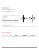
Programmable output resistance*
In its default state the Keysight B2961A/B2962A behaves like either an ideal voltage source with a negligibly small source resistance
or an ideal current source with a huge source resistance. The programmable output resistance feature allows you to specify either a
particular output resistance or a specific voltage versus current source characteristic. This feature is ideal for emulating a wide variety of
devices (such as batteries, photovoltaic cells, sensors, transducers, etc.) that are otherwise difficult to simulate.
Mode Constant or V/I Emulation
Programmable
resistance range:
Series resistance (Rs)
at voltage source
- (Load Resistance/2) ≤ Rs ≤ Load Resistance, for resistive load
Rs ≤ 25 Ω at 3 A range, ≤ 100 Ω at 1 A and 1.5 A ranges, ≤ 1 kΩ at 100 mA range, or ≤ 10 kΩ at other
ranges, Rs can be limited by capacitive load.
Shunt resistance (Rsh)
at current source
Load Resistance ≤ Rsh ≤ 2 GΩ, for resistive load
Rsh ≥ 10 MΩ at 10 nA and 100 nA ranges, ≥ 1 M Ω at other ranges, Rsh can be limited by capacitive load.
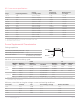
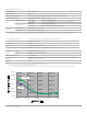
Emulation mode
Emulation mode allows you to program a non-linear resistance. You specify the desired voltage/current
characteristic using a tabular format
Max number of points: 16 (piecewise linear interpolation between points)
* Programmable output resistance is only available for DC output.