
User manual


Service and Maintenance 2
Verifying the Fuse Health
U1271A/U1272A Service Guide 35
Verifying the Fuse Health
It is recommended that you check the fuse(s) of the
multimeter before using it. Follow the instructions below to
test the fuses inside the multimeter.
1 Turn the rotary switch to the / position and
connect the red test lead to the input terminal.
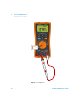
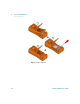
2 To test Fuse 1, place the tip of the test probe on the top
half of input terminal. Ensure that the probe tip
touches the metal inside the input terminal, as
shown in Figure 2- 1.
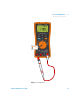
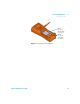
3 To test Fuse 2, place and touch the tip of the test probe
on the left half of input terminal. Ensure that the
probe tip touches the metal inside the input terminal,
as shown in Figure 2- 2.
4 Observe the reading on the instrument's display. Refer to
Table 2- 2 below for the possible readings that could
appear. Replace the fuse when is displayed.
NOTE
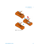
Refer to Figure 2-5 for the respective positions of Fuse 1 (10 × 35 mm,
440 mA/1000 V fast-acting fuse) and Fuse 2 (10 × 38 mm, 11 A/1000 V
fast-acting fuse).
Table 2 - 2 Fuse displayed readings
Current input
terminal
Fuse Part number Fuse rating
Displayed readings
Fuse healthy Replace fuse
1 2110-1400
440 mA/
1000 V
≈102 Ω OL
2 2110-1402
11 A/
1000 V
≈1.5 Ω OL
Smart