
User manual

1 Calibration Procedures
Using the Front Panel for Adjustments
28 U1271A/U1272A Service Guide
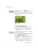
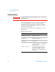
3 The primary display will show the reference value of the
calibration item.
Figure 1-9 rEF display
4 Configure each calibration item.
5 Use the , , , and keys to select the
calibration range.
6 Apply the input signal shown in the Reference Value
column of Table 1- 3. The analog bar graph displays the
input reading. There is no bar graph display for
temperature adjustment.
7 Use the , , , and keys to enter the
actual applied input values.
8 Press to start the adjustment. flashes in the
secondary display to indicate that the calibration is in
progress.
9 Upon completion of each adjustment value, the secondary
display will show . If the adjustment fails, the
multimeter will sound a long beep and the calibration
NOTE
While in the adjustment mode, press and simultaneously to
exit the adjustment mode.
S
h
i
f
t
V
i
e
w
E
s
c
A
u
t
o
T
r
i
g
H
o
l
d
P
e
a
k
M
a
x
M
i
n
A
u
t
o
R
a
n
g
e
Exit
Dual
Setup
NOTE
You are highly recommended to complete the adjustments in the same
order as shown in the appropriate table.
P
e
a
k
M
a
x
M
i
n
A
u
t
o
R
a
n
g
e
Exit
Dual
Setup
H
z
%
m
s
L
o
g