
User manual

Calibration Procedures 1
Using the Front Panel for Adjustments
U1271A/U1272A Service Guide 27
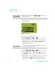
Adjustment procedure
1 Turn the rotary switch to the respective test function
position as shown in the adjustment input values table
(Table 1- 3).
2 Unsecure the instrument to enter the adjustment mode.
(See “Unsecuring the Instrument for Calibration” on
page 19).
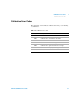
Resistance
SHORT SHORT SHORT Ω/COM terminals
30 MΩ OPEN OPEN terminals
10.000 MΩ 0.9 to 1.1 × Reference value
3 MΩ 3.0000 MΩ 0.9 to 1.1 × Reference value
300 kΩ 300.00 kΩ 0.9 to 1.1 × Reference value
30 kΩ 30.000 kΩ 0.9 to 1.1 × Reference value
3 kΩ 3.0000 kΩ 0.9 to 1.1 × Reference value
300 Ω 300.00 kΩ 0.9 to 1.1 × Reference value
30 Ω 30.000 Ω 0.9 to 1.1 × Reference value
Temperature K type 0000.0 °C
0 °C with ambient
compensation required
Note: Ensure the multimeter is turned on and stabilized for at least 60 minutes
with the K-type thermocouple connected between the multimeter and the
calibrator output terminal.
Diode
SHORT SHORT SHORT V/COM terminals
3 V 2.0000 V 0.9 to 1.1 × Reference value
Table 1 - 3 Adjustment input values (continued)
Test function Step Reference value Valid reference input
NOTE
Review the “Test considerations” and “Adjustment considerations” before
beginning the adjustment procedures.