
User manual


Calibration Procedures 1
Performance Verification Tests
U1271A/U1272A Service Guide 15
9
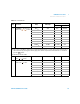
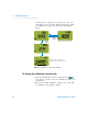
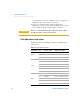
Resistance Turn the rotary
switch to the / position.
30 Ω
[2]
30 Ω N/A ±0.070 Ω
300 Ω
[2]
300 Ω ±0.65 Ω ±0.65 Ω
3 kΩ
[2]
3 kΩ ±0.0065 kΩ ±0.0065 kΩ
30 kΩ 30 kΩ ±0.065 kΩ ±0.065 kΩ
300 kΩ 300 kΩ ±1.55 kΩ ±0.65 kΩ
3 MΩ 3 MΩ ±0.0185 MΩ ±0.0185 MΩ
30 MΩ
[3]
30 MΩ ±0.365 MΩ ±0.365 MΩ
100 MΩ
[3]
100 MΩ ±2.10 MΩ N/A
300 MΩ
[3]
120 MΩ N/A ±9.70 MΩ
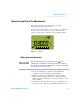
[2] The accuracy of the 300 Ω to 3 kΩ range is specified after the Null function is used to subtract the test lead resistance
and thermal effect (by shorting the test leads). Apply a 0 Ω calibrator output and allow the multimeter to settle before
press the button.
[3] The RH is specified for <60%.
10
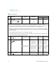
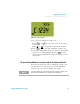
Diode Turn the rotary switch
to the / position.
3 V 3 V 0.0155 V 0.0155 V
11
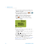
Capacitance Turn the rotary
switch to the position.
10 nF 10 nF ±0.105 nF ±0.105 nF
100 nF 100 nF ±1.02 nF ±1.02 nF
1000 nF 1000 nF ±10.2 nF ±10.2 nF
10 μF10 μF ±0.102 μF ±0.102 μF
100 μF100 μF ±1.02 μF ±1.02 μF
1000 μF 1000 μF±10.2 μF±10.2 μF
10 mF 10 mF ±0.102 mF ±0.102 mF
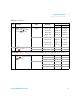
Table 1 - 2 Functional Test
Step Test function Range 5520 output
Error from nominal 1 year
U1271A U1272A
Smart
S
c
a
l
e
N
u
l
l
Auto