
User manual

Characteristics and Specifications 4
Electrical Specifications
U1190A Series User’s Guide 67
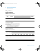
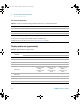
Continuity 600.0 0.1 0.8% + 5 0.8% + 5 0.8% + 5 0.8% + 5 95 A 1.4 V
Notes for continuity specifications:
1 Overload protection: 600 Vrms for short circuits with <0.1 A current
2 Built-in buzzer beeps continuously when the resistance measured is less than 30 . Resistance measurements above
200 are considered open. For resistance measured between 30 and 200 (30 reading 200 ), the built-in
buzzer may beep depending on the device-under-test.
3 Continuity indicator: 2.7 kHz tone buzzer
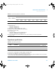
Diode 1.500 V 0.001 V 1.0% + 3 1.0% + 3 1.0% + 3 1.0% + 3 0.3 mA 1.8 V
Notes for diode specifications:
1 Overload protection: 600 Vrms for short circuits with <0.4 mA current
2 Built-in buzzer beeps continuously when the voltage measured is less than 100 mV and beeps once for forward-biased
diode or semiconductor junctions measured between 0.3 V and 0.8 V (0.3 V reading 0.8 V).
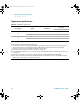
Current
60.00 µA 0.01 µA - - - 1.0% + 5 - -
600.0 µA 0.1 µA - - - 1.0% + 5 - -
60.00 A 0.01 A - - - 2.0% + 5 - -
600.0 A 0.1 A - - - 2.0% + 5 - -
Notes for DC current specifications:
1 60 A to 600 A ranges are for current clamp measurements.
2 60 µA to 600 µA ranges are for digital multimeter measurements.
3 Overload protection for 60 A to 600 A range: 600 Arms
4 Input impedance for 60 µA to 600 µA range: 4.2 k
5 Position error: 1% from reading
6 The accuracy is specified after the Null function is used to subtract the test lead resistance and thermal effect (by shorting
the test leads).
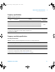
Table 4 - 1 DC specifications (continued)
Function Range Resolution
Accuracy Test current
Open
voltage
U1191A U1192A U1193A U1194A (where applicable)
U119XA UG.book Page 67 Thursday, September 15, 2011 4:03 PM