
User manual

2 Making Measurements
Measuring Resistance
34 U1190A Series User’s Guide
Measuring Resistance
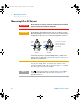
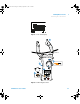
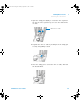
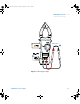
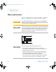
Set up your clamp meter to measure resistance as shown in
Figure 2- 9. Probe the test points, and read the display.
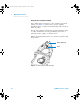
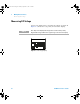
Figure 2-8 Resistance display
CAUTION
To avoid possible damage to your clamp meter or to the equipment
under test, disconnect the circuit power and discharge all high-voltage
capacitors before measuring resistance.
NOTE
Resistance (opposition to the current flow) is measured by sending a small
current out through the test leads to the circuit under test. Because this
current flows through all possible paths between the leads, the resistance
reading represents the total resistance of all paths between the leads.
Resistance is measured in ohms ().
NOTE
Keep the following in mind when measuring resistance.
• The test leads can add 0.1 to 0.2 of error to resistance
measurements. To test the leads, touch the probe tips together and
read the resistance of the leads.
• Because the clamp meter’s test current flows through all possible
paths between the probe tips, the measured value of a resistor in a
circuit is often different from the resistor’s rated value.
• The resistance function can produce enough voltage to forward-bias
silicon diodes or transistor junctions, causing them to conduct.
U119XA UG.book Page 34 Thursday, September 15, 2011 4:03 PM