
User manual

Introduction 1
Your Clamp Meter in Brief
U1190A Series User’s Guide 21
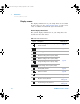
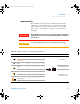
Input terminals
The terminal connections for the different measurement
functions of your clamp meter are described in the table
below. Observe the rotary switch position of your clamp
meter before connecting the test leads to the connector
terminals.
WARNING
Ensure that the probe accessories are connected to the correct input
terminals for the selected measurement function before starting any
measurement.
CAUTION
To avoid damaging this device, do not exceed the rated input limit.
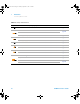
Table 1 - 7 Terminal connections for different measuring functions
Legend Functions U1194A U1193A U1192A U1191A Input terminals Overload protection
AC V
✔✔✔✔
600 Vrms
Frequency
(voltage path)
✔✔✔
-
DC V
✔✔✔✔
Diode
✔✔✔✔
600 Vrms for short
circuit current <0.4 A
Capacitance
✔✔✔
-
600 Vrms for short
circuit current <0.1 A
Resistance
✔✔✔✔
Continuity
✔✔✔✔
Non-contact
voltage detector
✔✔✔
-
Te m p e r a t u r e
✔
---
U119XA UG.book Page 21 Thursday, September 15, 2011 4:03 PM