
User manual

Introduction 1
Your Clamp Meter in Brief
U1190A Series User’s Guide 15
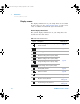
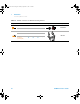
Rotary switch
The measurement functions for each rotary switch position
are described in Table 1- 3 on page 16. Turning the rotary
switch changes the measurement function and resets all
other measurement options.
Each position of the U1191A, U1192A, U1193A, and U1194A
rotary switches (shown in Figure 1- 3) is described in
Table 1- 3. Click the respective “Learn more” pages for more
information on each function.
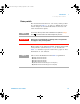
NOTE
Some rotary switch positions have a shifted function printed in orange.
Press to switch between the shifted and primary function.
WARNING
Remove the test leads from the measuring source or target before
changing the rotary switch position.
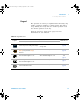
NOTE
A list of some of the abbreviations used in Table 1-3 is given below.
•AC A: AC current measurement
•DC A: DC current measurement
•AC V: AC voltage measurement
•DC V: DC voltage measurement
•AC A: AC current measurement (up to microamperes)
•DC A: DC current measurement (up to microamperes)
U119XA UG.book Page 15 Thursday, September 15, 2011 4:03 PM