Owner’s Manual Alliance A7 Upright Customer Service (888) 340-0482 Keys Fitness Products 4009 Distribution Drive Suite 250 Garland, TX 75041 www.keysfitness.com Model Name : A7u Serial Number : Write down for future reference. Serial number is located under unit.
Table of Contents Important Safety Information 3 Before You Start 4 Assembly 5-9 Console Profiles 10 Console Buttons 11 Program Operation 12-13 Program Profiles 14 Monitoring Your Heart Rate 15-16 Change to MPH or KPH 17 Bike Operation 18 Parts List 19 Exploded View 20 Warranty Information 21 2
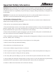
Important Safety Information WARNING! Before using this unit or starting any exercise program, consult your physician. This is especially important for persons over the age of 35 and/or persons with pre-existing health problems. The manufacturer or distributor assumes no responsibility for personal injury or property damage sustained by or through the use of this product.
Before You Start Thank you for purchasing the Alliance A7 Upright! This quality product you have chosen was designed to meet your needs for cardiovascular exercise. Before you start, please read the Owner's Manual and become familiar with the operation of your new unit. Remember to take the time to perform the stretching exercises provided to avoid injury. If you are taking medication, consult your physician to see if the medication will affect your exercise heart rate.
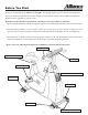
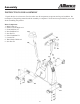
Assembly INSTRUCTIONS FOR ASSEMBLY Unpack the box in a clear area. Check to make sure all components are present and in good condition. Do not dispose of the packing material until the assembly is completed. Tools have been provided for you to use when assembling this product. Main Components: 1. Main Frame A1 2. Pedals Left and Right A14 3. Front Stabilizer C1 4. Rear Stabilizer D1 5. Seat Pad E1 6. Pulse Handlebar H1 7. Console H6 8. Water Bottle Holder A2 9.
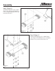
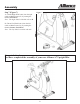
Assembly Step 1 (Figure 1) Attach Rear Stabilizer (D1) to Main Frame (A1) using two Flat Washers (C9), two Spring Washers (C10), and two Hex Nuts (C11). Figure 1 Step 2 (Figure 2) Attach Front Stabilizer (C1) to Main Frame (A1) using two Flat Washers (C9), two Spring Washers (C10), and two Hex Nuts (C11).
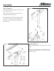
Assembly Step 3 (Figure 3) Figure 3 A) Connect Upper Wire Harness (H8) to Lower Wire Harness (A39). Note: Upper Wire Harness will be located inside the Console Tube (H1). B) Slide Console Tube (H1) into Main Frame (A1) and secure using four Flat Allen Head Bolts (H7). Insert Decoration Cap (B4) into each bolt hole. Step 4 (Figure 4) Figure 4 A) Connect Upper Wire Harness (H8) to Console (H6). B) Secure Console (H6) to Console Tube (H1) using six Round Head Screws (A36) and six Flat Washers (A24).
Assembly Step 5 (Figure 5) Figure 5 Attach Seat Pad (E1) to Seat Post (E2). Step 6 (Figure 6) Figure 6 Slide Seat Post (E2) into Main Frame (A1) and secure using Locking Pop Pin Knob (E4).
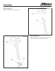
Assembly Step 7 (Figure 7) Figure 7 A) Thread Right Pedal (A14) into the right crank on Main Frame (A1) by turning the threads Clock-Wise. Note: The Right Pedal is Marked with an R.. B) Thread Left Pedal (A14) into the left crank on Main Frame (A1) by turning the threads Counter Clock-Wise. Note: The Left Pedal is marked with an L. Congratulations! You have completed the assembly of your new Alliance A7 Upright Bike.
Console Profiles The Alliance A7r has an internal generator that provides electrical power to console display. You never need batteries or have to plug it in. Just simply pedal over 25 RPM to activate the console. There are 3 options for accessing programs: 1. AT TEST: AT Measurement 2. HRC Mode: Cardio, Fitness Training, Target Heart Rate and Fat Burn 3.
Console Buttons QUICK START: Press this button to enter MANUAL program. AT TEST: Press this button to enter AT TEST mode. RESET: Clears current setup variables and goes back to the beginning of setup mode. PAUSE / RESUME: Save and readout the data of current workout situation. ENTER: Confirm the input data for age, weight, program mode, resistance level, and workout time. PLUS (+): Increases the value for age, weight, resistance levels, and workout time.
Program Operation Monitoring Heart Rate: Heart Rate Handgrips: Place you palms onto the metal sensor plates, after few second your heart rate should be displayed in the window. Heart Rate Transmitter Strap: Adjust the strap to proper length. Wear directly against your skin around chest. Some moisture is need between the Transmitter and your skin prior to your workout. Once you start the workout, your heart rate will be displaced in heart rate window.
Program Operation HRC Mode: (Heart Rate Control) 1. Use + or - to move the LED Indicator to select one of the following programs: CARDIO, FITNESS TEST, TARGET HEART RATE, OR FAT BURN. You can also use the KEY PAD to choose one directly. 2. Press ENTER 3. Use + or - to increase or decrease the user weight, or use the KEY PAD to type it in. 4. Press ENTER 5. Use + or - to input the user’s AT HR (heart rate), or use the KEY PAD to type it in. 6. Press ENTER 7.
Program Profiles HRC Programs Cardiovascular: A program designed to keep your workout heart rate value at AT HR x 110%. Fitness Test: A program designed to keep your workout heart rate value at AT HR x 100%. Target Heart Rate: A program designed to keep your workout heart rate value at AT HR x 95%. Fat Burn: A program designed to keep your workout heart rate value at AT HR x 90%. Constant Mode Programs Manual Mode: A program designed to be controlled by the user.
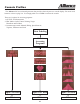
Monitoring Your Heart Rate Monitoring Your Heart Rate To obtain the greatest cardiovascular benefits from your exercise workout, it is important to work within your target heart rate zone. The American Heart Association (AHA) defines this target as 60%-75% percent of your maximum heart rate. Your maximum heart rate may be roughly calculated by subtracting your age from 220. Your maximum heart rate and aerobic capacity naturally decreases as you age.
Monitoring Your Heart Rate TARGET HEART RATE ZONE 100% 200 195 190 185 180 Serious athletic training range 85% 170 166 162 157 Cardiovascular conditioning range 75% 150 146 143 139 153 135 Fat burning range 60% 120 20 117 25 114 30 111 35 108 40 175 149 131 105 45 AGE 16 170 145 128 165 140 124 160 136 120 102 99 96 50 55 60 155 132 116 93 65
Change to MPH or KPH Change to MPH (Miles Per Hour) or KPH (Kilometers Per Hour): 1. With the unit off press and hold “0” on the key pad. 2. Start pedaling the bike. “UNIT=KG” OR “UNIT=LB” will be displayed in the upper LED window. 3. Use the key pad to indicate which unit of measure you would like to use. Press “1” for KG and to change distance to KPH. Press “2” for LB and to change distance to MPH. 4. Stop pedaling the unit until the screen shuts off to accept the changes.
Bike Operation Seat Adjustment To raise or lower the seat height, start by pulling out the pop pin knob. Next, raise or lower the seat post to the proper position. Then, release the pop pin knob to the pre-set position hole. It is important to ensure that the pop pin knob is locked in one of the pre-set position holes on the seat post. Refer to Figure 1.
Parts List A7u Parts List Rev C REF# KEYS PART# DESCRIPTION QTY. REF# KEYS PART# DESCRIPTION QTY. A1 323-00165 A7u Frame Assembly 1 C10 302-00277 A7r & A7u Spring Washer SW8 A2 310-00123 A7r & A7u Water bottle Holder 1 C11 302-00245 A7u Hex Screw M6*1.25*50 4 A3 302-00311 A7u Seat post bolt 2 C12 302-00252 A7r & A7u Insert Nut M10*1.
Exploded View 20
Warranty Information KEYS FITNESS PRODUCTS, LP LIMITED WARRANTY PRODUCT: A7u HOME USE WARRANTY: Parts: Electronics: 3 Years 2 Years LIGHT INSTITUTIONAL: Parts: Electronics: 2 Years 2 Years Labor: 1 Year Labor: 1 Year This Limited Warranty applies in the United States and Canada to products manufactured or distributed by Keys Fitness Products, LP (“Keys”) under the KEYS brand name. The warranty period to the original purchaser is listed above in the table.
Customer Service (888) 340-0482 Keys Fitness Products 4009 Distribution Drive Suite 250 Garland, TX 75041 www.keysfitness.