
User guide


4
SL-VHS-IM-E
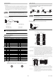
* Refer to the following diagram for detection zone and protection zone.
When determining a specific installation distance, refer to the following values including the installa-
tion tolerance.
■ Wiring for interlock selection input
■ Wiring for EDM function
■ Wiring unless EDM function is applied
■ Wiring for muting device
■ Wiring for muting lamp
■ Wiring for Override function
Installation measures against glossy surface
Operating distance “X” Minimum installation distance “Y”
Less than 3 m 0.13 m
3 m or more X/2 x tan5 ° = 0.0437 X
OSSD circuit Diagram
Wiring and Function
Protection
height
Specified detection capability
Protection zone
Operating distance
Detection zone
Detection
height
Transmitter
Receiver
5
o
Mirror surface
X
Y
Mirror surface
X
Y
Transmitter
Receiver
External
device
Main
circuit
+24 V
0 V
10
OSSD
Ω
10 Ω
External
device
Main
circuit
+24 V
0 V
OSSD
Main
circuit
+24 V
0 V
Input
Output
Main
circuit
+24 V
0 V
OSSD PNP output circuit OSSD NPN output circuit
Input circuit Output circuit
Receiver
Main
circuit
Blue
Brown
Ye l l o w (reset input)
0 V
+24 V
Receiver
Main
circuit
Blue
Brown
Ye l l o w (reset input)
0 V
+24 V
0 V
+24 V
Transmitter
Main
circuit
Blue
Brown
Pink (interlock mode selection input)
Common for a PNP/NPN output type cable
When using a PNP output type cable When using an NPN output type cable
Red
Brown
Short-circuit
current: 10mA
Device 1
Device 2
Blue
Receiver
Main
circuit
0 V
+24 V
Red
Brown
Short-circuit
current: 10mA
Device 1
Device 2
Blue
Receiver
Main
circuit
0 V
+24 V
When using a PNP output type cable When using an NPN output type cable
Red (AUX output)
Input device
Brown
Blue
Transmitter
Main
circuit
Red (EDM input)
Brown
Blue
Receiver
Main
circuit
0 V
+24 V
0 V
+24 V
0 V
+24 V
Red (EDM input)
Brown
Blue
Receiver
Main
circuit
Input device
Brown
Red (AUX output)
Blue
Transmitter
Main
circuit
0 V
+24 V
When using a PNP output type cable When using an NPN output type cable
Light blue
Brown
Blue
Light blue/
Black
Receiver
(Muting input 2)
(Muting input 1)
Muting device 1
Muting device 2
Short-circuit current: 2.5 mA
Main
circuit
0 V
+24 V
Brown
Blue
Light blue
Light blue/Black
(Muting input 2)
(Muting input 1)
Receiver
Muting device 1
Muting device 2
Short-circuit current: 2.5 mA
Main
circuit
0 V
+24 V
When using a PNP output type cable When using an NPN output type cable
Ye l l o w/Black
Muting
lamp
Brown
Blue
Monitor circuit
Main
circuit
Receiver
0 V
+24 V
Common for a PNP/NPN output type cable
Ye l l o w
Brown
Blue
Red/Black
(Override input)
(Reset input)
Receiver
Main
circuit
Short-circuit current: 2.5 mA
0 V
+24 V
Brown
Blue
Ye l l o w
Red/Black
(Override input)
(Reset input)
Short-circuit current: 2.5 mA
Receiver
Main
circuit
0 V
+24 V
When using a PNP output type cable When using an NPN output type cable