
User guide


3
SL-VHS-IM-E
(1) Cable length
When using the unit connection cable, junction cable, and extension cable together, the sum of the
length for all type of cables must be 30 m or less. This limitation is applicable to each the transmitter
and receiver respectively. Since up to 3 SL-VHS units (230 beam axes) can be connected in series,
up to 2 sets of series connection cables are required. Two sets of the SL-VS10 (cable length: 10 m)
cables can be used. In this case, the sum of the length of all type of cables, including the series
connection cable, must be 50 m or less. This limitation is also applicable to each transmitter and
receiver respectively.
• Cables must be within the lengths specified. Failure to follow this specification may cause
improper operation of safety function, and may cause dangerous situation.
•
The series connection cable cannot be cut or extended. If the cable is cut or extended, safety
features may not operate properly. Do not allow this to happen as it is extremely dangerous.
(2) Minimum cable bending radius : 5 mm
(3) Identification of connector cables
Cables can be identified by the colors of their connectors and their cable insulation.
1. Cable Insulation colors
Cables for Transmitter : Cable insulation in grey
Cables for Receiver : Cable insulation in black
2. Connector colors
PNP output type cables : Black connectors
NPN output type cables : Grey connectors
Series connection cables : Black connectors
The PNP output type cable and the NPN output type cable cannot be used together at the same time.
Use only one of these types according to the operation condition.
Be sure to connect the unit connection cable for receiver to the SL-VHS receiver and the unit connec-
tion cable for transmitter to the SL-VHS transmitter.
■ Simple function type
■ Multi-function type
• The ON/OFF state of the state information output 1 indicates if the SL-VHS is in the lockout
condition.
• The ON/OFF state of the state information output 2 indicates if the SL-VHS is in the muting
condition.
• The pin assignment of the unit connection cable (for extension) is as follows.
1
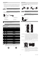
The unit connection cable for transmitter (cable insulation is grey) must be connected to the transmitter as shown below. Sim-
ilarly, the unit connection cable for receiver (cable insulation is black) must be connected to the receiver as shown below.
Recommended tightening torque : 0.3 N·m
Minimum cable bending radius : 5 mm
Transmitter Receiver
• Do not remove the grey gasket installed on the connector. This gasket is necessary to ful-
fill the requirement of IP65.
•
Connect the unit connection cable to the connector receptacle on the lower part of the SL-VHS.
Removing the connector cover on the upper part of the SL-VHS and connecting the unit con-
nection cable may result in an SL-VHS failure.
2 One ferrite core must be put on the unit connection cable for the transmitter.
*1 The side where the connector cover has already been installed at shipment is the top side.
Beam center-line : An optical path joining the optical center of the emitting element on the transmit-
ter to the optical center of the corresponding receiving element on the receiver.
the SL-VHS must be installed so that the beam center-line mark on the transmit-
ter and that on the receiver face one another and are located at the same height.
Detection height : The height from the top beam center-line to the bottom beam center-line (length).
Protection height : An object approaching the detection zone from the top of the detection height is first
detected at point A, which is the distance of the detection capability from the top of the
detection height. The equivalent position on the bottom is called point B. The height from
the top edge of the specified detection capability that exists at point A to the bottom edge
of the specified detection capability that exists at point B is called a "protection height".
The following calculation formula can be defined:
Protection height = "Detection height" + 2 x "the specified detection capability"–"beam axis diameter".
*
Refer to the following diagram for an explanation of beam center-line, detection height and protection height.
Detection zone : The zone in which the specified detection capability can be detected. The
detection zone of the SL-VHS indicates a square area formed with the detection
height and the operating distance. When a part or whole of the specified detec-
tion capability is present in this area, the light of the SL-VHS is blocked, and then
the OSSD goes to OFF state.
Protection zone : The square area formed with the protection height and the operating distance,
which is broader than the detection zone. When a whole of the specified detec-
tion capability is present in this area, the light of the SL-VHS is blocked, and then
the OSSD goes to OFF state.
Cable specification
Connector pin assignment
Transmitter Receiver
Pin No. Wire color Assigned function Pin No. Wire color Assigned function
1PinkInterlock mode selection input 1WhiteOSSD 2
2Brown+24 V 2Brown+24 V
3VioletWait input 3BlackOSSD 1
4GreenNot used 4YellowRESET input
5 Orange Communication cable 1 (RS485_+) 5OrangeCommunication cable 1 (RS485_+)
6
Orange/
Black
Communication cable 2 (RS485_-) 6
Orange/
Black
Communication cable 2 (RS485_-)
7Blue0 V 7Blue0 V
8RedAUX (auxiliary) output 8RedEDM input
9GreyState information output 1 9Red/BlackOverride input
10 Grey/Black State information output 2 10
Ye l l o w /
Black
Muting lamp output
11 Pink/Black Alert output 11 Light blue Muting input 1
12
White/
Black
Clear/Blocked Output 12
Light blue/
Black
Muting input 2
Danger
2. Connector
1. Cable insulation
NOTE
Reference
6
10
11 12
9
8
7
12
3
4
5
5
837
6
1
2
4
Simple-function cable male pin assignment Multi-function cable male pin assignment
Cable connection
Part Description
grey
M2.6
screw
black
M2.6
screw
Push the cable
into the
g
roove.
Push the cable
into the groove.
Caution
Within 200 mm
Ferrite core
(diameter: 18.5 mm, length: 34 mm)
Unit connection cable
Transmitter
Attach to the transmitter
LEVEL
WAIT
FUNCTION
OSSD
INTER
LOCK
ø25 (0.98")
SL-V08HS
1
2
3
4
5
LEVEL
MUTE1
MUTE2
OSSD
INTER
LOCK
1
2
3
4
5
ø25 (0.98")
SL-V08HS
Detection
surface
Connector receptacle
Beam center-line mark
(lower)
Beam center-line mark
(upper)
Indicators
Detection
surface
Bottom
To p
Connector cover
Installation reference mark
Installation reference mark
*
1
SL-VHS main unit
ReceiverTransmitter
Specified detection capability (position A)
Specified detection capability (position B)
Protection heightDetection
height
Beam center-line
Beam center-line mark
a
a: Beam axis spacing
b: Beam axis diameter
c: Detection capability
b
c