
Owner manual


5
LS-Navigator-M-NO5-E
5-26
5-10 Setting the Measurement Conditions for the Program
1
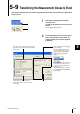
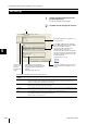
Click on the [Settings list] tab in the
program setting area.
A list of the set parameters appears in the
[Settings list] window.
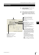
2
Copy the settings to clipboard. Paste the
settings in another application, such as
Excel.
Reference
The parameters that have been changed from their
default values are displayed in blue.
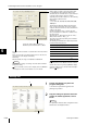
Settings list
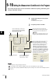
Analog voltage is output for the measurement value.
For standard value mode: When the limit mode is
standard value, the standard value is represented by 0
V, and the output voltage is greater or smaller
depending on the deviation. Select one of the following
values from the pull-down menu.
Valid values:
1, 2, 5, 10, 20, 50, 100, 200, 500, 1000, 2000, 5000,
10000 µm/V
Threshold m
ode: When the limit mode is threshold
mode, set the measurement valu
es that you want to
output at +10 V and -10 V. These values determine the
scaling for the output.
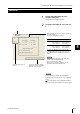
Set the measurement values so that the absolute
value of their difference satisfies the conditions of the
following formula.
Absolute value of { (Measurement value for +10 V) -
(Measurement value f
or -10V) } X
The
value for X changes depending on the minimum
display unit setting.
The following chart indicates the relationship between
X and the minimum display unit.
For more details, see the “Analog Output Settings”
section in the “User’s Manual” for each controller.
Set the same values for [Units] and [Minimum display
unit] in the settings f
or the controller and LS-Navi
gator.
(Refer to Page 5-5.)
Minimum display unit (mm) X (mm)
0.00001, 0.00002, 0.00005 0.02
0.0001, 0.0002 0.2
0.001, 0.01, 0.1 2
0.01, 0.02, 0.05 20
0.1, 0.2 200
1 2000
>_
Copies the output settings from OUT1 or
OUT2 and pastes them into OUT1 or OUT2.
The entered value is added to or subtracted from the measurement
value.
When an offset value is set while using the auto zero function, the
offset appears on the display momentarily.
Valid range:
With the defaults, the range is -99.99999 to 99.99999 mm.
Reference
The offset value changes according to the units and the minimum
display unit setting.
For more details, see the sections “Display Unit” and “Minimum
Display Unit” in the “User’s Manual” for each controller.
2
1