
Owner manual


5
5-23
LS-Navigator-M-NO5-E
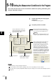
5-10 Setting the Measurement Conditions for the Program
1
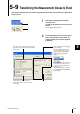
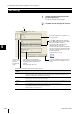
Click on the [Calibration] tab in the
program setting area.
The [Calibration] window appears.
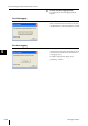
2
Set [Logic calibration] for area 1 and area
2.
Note
These settings are effective when [Calibration
Settings ] for the controller is set to logic calibration
mode.
For more details, see the “Calibration Settings”
section in the “User’s Manual” for each controller.
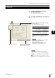
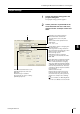
Calibration
Select the area (area 1 or
area 2).
Enter the values for two points (target 1 and target
2) on the workpiece.
The values are displayed as follows:
The value for calibration span is automatically
calculated after the above values are entered.
The calibration span is display
ed as a ref
erence
value.
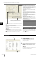
Note
When setting the calibration mode, enter values
that meet the following relationship:
T1-A < T2-A and T1-B < T2-B
Set the values so that the calibration span is
greater than 0.5 and smaller than 2.0.
Before calibration After calibration
FirstT1-A: Displayed
value for target 1
before calibration
T1-B: Displayed
value for target 1
after calibration
Second T2-A: Displayed
value for target 2
before calibration
T2-B: Displayed
value for target 2
after calibration
Copies the calibration settings
from area 1 or area 2 and pastes
them into area 1 or area 2.
1