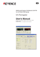
96136E Setting and Support Software LS-H1W for LS-7600/7000 Series LS-Navigator User’s Manual Read this manual before using the system in order to obtain full performance. Keep this manual in a safe place for future reference.
Safety Precautions This manual describes the functions and usage for LS-Navigator, the setting and support software LS-H1W for LS-7600/7000 series. Read this manual carefully before starting to use the software to ensure the optimum performance and full functionality of the LS-Navigator. Keep this manual in a safe place for future reference. Symbols 2 The following symbols and conventions alert you to important messages.
Terms of the Software License Agreement LS-Navigator is available to you provided that you agree with the following license agreement. Read the following agreements carefully before using this software. By using the LS-Navigator, you signify that you agree with the statements herein and the contract is accepted. License agreement 1. License of use KEYENCE grants the user the nonexclusive right to use this software in accordance with terms of this agreement. 2.
MEMO 2 LS-Navigator-M-NO0-E
Organization of the Manual Chapter 1 LS-Navigator Overview Chapter 2 Chapter 3 Chapter 4 Chapter Getting Started Names and Functions of Parts of the Window Operation Flow from Startup to Shutdown 5 Functions and Operation Procedures Appendix Appendix LS-Navigator-M-NO0-E This chapter describes the key functions, the conditions for use, and the system environment for the LS-Navigator.
MEMO 4 LS-Navigator-M-NO0-E
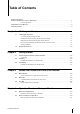
Table of Contents Safety Precautions Terms of the Software License Agreement. . . . . . . . . . . . . . . . . . . . . . . . . . . . . . . . . . . . . . . . . . . . . . . 1 License agreement . . . . . . . . . . . . . . . . . . . . . . . . . . . . . . . . . . . . . . . . . . . . . . . . . . . . . . . . . . . . 1 Organization of the Manual. . . . . . . . . . . . . . . . . . . . . . . . . . . . . . . . . . . . . . . . . . . . . . . . . . . . . . . . . . . 3 Table of Contents . . . . . . . . . . . . . . . . . .
Chapter 5 Operating and Setting Functions 5-1 Setting and Changing the Connection . . . . . . . . . . . . . . . . . . . . . . . . . . . . . . . . . . . . . . 5-2 Setting and changing the connected controller. . . . . . . . . . . . . . . . . . . . . . . . . . . . . . . . . . . . . 5-2 5-2 Reading and Saving Setting Files . . . . . . . . . . . . . . . . . . . . . . . . . . . . . . . . . . . . . . . . . 5-3 Reading setting files . . . . . . . . . . . . . . . . . . . . . . . . . . . . . . . . . . . . . . . .
1 LS-Navigator Overview This chapter describes the key functions, the setting conditions, and the system environment for the LS-Navigator. LS-Navigator-M-NO1-E 1-1 LS-Navigator Overview....................................... 1-2 1-2 System Environment ..........................................
1-1 LS-Navigator Overview This chapter describes the functions and setting conditions for the LS-Navigator. 1 Controller program setting function 1. Receives program settings for the controller on the computer and allows the user to verify the data. 2. Sends settings created on the computer to the controller and sets the program. 3. Reduces the time for settings with copy and paste functions when making settings for multiple controllers or programs.
1-1 LS-Navigator Overview Backup and restore functions for all controller settings 1. Reads and backs up the settings for all 16 programs on the controller (all of the parameters for limit settings, calibration settings, area settings, and output settings) and the environment settings on the computer. 2. Restores the settings from the backup file created on the computer, in the event that the settings are erased 1 from the controller.
1-1 LS-Navigator Overview Function for transferring measurement values to an Excel sheet The measured values that are received from the controller can be transferred to an Excel sheet with the specifications from the specified logging method 1 Logging methods 1. Click logging : Transfers the measurement values when the button is clicked. 2. Timer logging : Transfers the measurement values at specified intervals. 3.
1-2 System Environment The following system requirements are necessary to use LS-Navigator.
MEMO 1 1-6 LS-Navigator-M-NO1-E
2 Getting Started This chapter describes how to connect the computer and the controller, and how to install or uninstall LS-Navigator. LS-Navigator-M-NO2-E 2-1 Connecting the Controller and the Computer ..... 2-2 2-2 Installing ............................................................. 2-3 2-3 Uninstalling .........................................................
2-1 Connecting the Controller and the Computer This section describes how to connect the controller and the computer by using RS-232C. Note This operation varies depending on the location and direction of the RS-232C port on the computer. Refer to the manual that comes with the computer when connecting the RS-232C cord. 2 Connecting Connect the controller (LS-7600/7500/7000) and the computer by using RS-232C. Use the cord OP-35382 (D-sub 9-pin) or OP-25253 (D-sub 25-pin) for connection.
2-2 Installing This section describes the procedures for installing LS-Navigator to a computer. Example of installation on Windows XP This procedure describes how to install the software on Windows XP. 2 • Close all active applications before starting the installation. • When installing on Windows 7, Windows Vista, Windows XP Professional Edition or Windows 2000 Professional, log in with a user name that has Administrator rights.
2-2 Installing 4 Enter the information into [User Name] and [Company Name], and then click on the [Next] button. The [Destination Folder] dialog appears. • The default setting installs the software to "C:\Program Files\KEYENCE\LS-Navigator". • To install the software to a different folder, click on the [Change] button and select the folder in the [Change Current Destination Folder] dialog. 5 Click on the [Next] button. A window appears with the message that the program is ready to be installed.
2-2 Installing 7 The program is installed. 2 8 When installation finishes, the [InstallShield Wizard Completed] window appears. Click on the [Finish] button to complete the process. An [LS-Navigator] shortcut appears on the Desktop, and [LS-Navigator] appears under [KEYENCE Applications] in the Windows [Start] menu. 8 Note The help file for this software was created in PDF file format.
2-3 Uninstalling This section describes the procedures for uninstalling LS-Navigator from a computer. Example of uninstallation on Windows XP This procedure describes how to uninstall the software on Windows XP. 2 • Close all active applications before starting the uninstall process. • When uninstalling on Windows 7, Windows Vista, Windows XP Professional Edition or Windows 2000 Professional, log in with a user name that has Administrator rights.
3 Names and Functions of Parts of the Window This chapter describes the names and functionsof each part of the LS-Navigator window. LS-Navigator-M-NO3-E 3-1 Main Window ...................................................... 3-2 3-2 Menu Bar ............................................................ 3-3 3-3 Tool Bar ..............................................................
3-1 Main Window This section describes the main window. Names and functions of parts of the main window Communication and file operation area Initializes parameters, opens or saves setting files, and receives or sends controller parameters. 3 Menu bar Displays the operational menus for LS-Navigator. Unit setting area Set and change the units and minimum display unit for the selected program. For more details, see “Setting and Changing Units” (Page 5-5).
3-2 Menu Bar This section describes the command names and the functions for each menu in the menu bar. Command names and functions for each menu File menu Command name Function Reference page Open file Reads a saved setting file for the controller. Page 5-3 Save file Saves a setting file for the controller. Page 5-4 Exit Exits LS-Navigator. Page 4-5 Command name Function Reference page Measure view Displays the measurement value for the controller.
3-2 Menu Bar Settings menu Command name Function Reference page Change connection Change the model of the connected controller (LS-7600/LS7500 series or LS-7000 series). Page 5-2 Reference • Changing the connected model sets the following setting data to the default values: Limit settings, Calibration settings, Area settings, and Output settings. • Changing the connected model also changes the extension for the backup file.
3-3 Tool Bar This section describes the names and functions of each tool in the tool bar. Names and functions of the tools Tool bar 3 Connection Tool name Function Reference page Connection Displays the model of the currently connected controller. Page 5-2 Tool name Function Reference page Measurement view Displays the measurement values acquired from the controller in the [Measure view] window.
3-3 Tool Bar Restore settings Tool name Function Reference page Restore settings Restores all of the settings for the controller from a backup file saved on the computer. Page 5-11 Tool name Function Reference page Communication settings Sets the communication conditions for the RS-232C connection that connects the computer and the controller.
4 Operation Flow from Startup to Shutdown This chapter describes the basic flow of operations for the LS-Navigator from startup to shutdown. LS-Navigator-M-NO4-E 4-1 Basic Flow of Operations.................................... 4-2 4-2 Basic Procedures for Operation .........................
4-1 Basic Flow of Operations The following chart shows the flow of operations for the LS-Navigator from startup to shutdown. Operation flow from startup to shutdown Connect the controller and the computer by using RS-232C. Page 2-2 Start up the controller and set it to [Measurement] mode. Next, start up the computer. Page 1-4 4 Start up LS-Navigator.
4-2 Basic Procedures for Operation This chapter describes the basic procedures for operation for the LS-Navigator from startup to shutdown. Basic procedures from startup to shutdown 1 Run LS-Navigator by double clicking on the [LS-Navigator] shortcut icon on the Desktop or by clicking on [All Programs] in the Start menu and selecting [LSNavigator] from [KEYENCE Application]. The “Welcome” message appears.
4-2 Basic Procedures for Operation 3 Select the model of the controller connected to the computer from the following options. LS-7000 Series, LS-7600/LS-7500 Series Note The model of the controller connected to the computer must be the same as the model selected in this window on LS-Navigator. 4 4 4 3 Select the method for reading the setting contents from the following options.
4-2 Basic Procedures for Operation 5 Perform necessary actions such as displaying the measurement values, sending or receiving setting files, setting the measurement conditions for the program, or backing up and saving the settings. For more details, see “Chapter 5: Operating and Setting Functions” (Page 5-1). Main window 4 6 Select [Exit] from the [File] menu to exit LSNavigator.
MEMO 4 4-6 LS-Navigator-M-NO4-E
5 Operating and Setting Functions This chapter describes how to operate the functions and perform settings in the LS-Navigator. 5-1 Setting and Changing the Connection................ 5-2 5-2 Reading and Saving Setting Files ...................... 5-3 5-3 Setting and Changing Units................................ 5-5 5-4 Viewing the Measurement Value ........................ 5-6 5-5 Sending, Receiving, and Initializing Settings...... 5-7 5-6 Backing up or Restoring All Settings ................
5-1 Setting and Changing the Connection This section describes how to set and change the controller connected to the computer. Setting and changing the connected controller 1 1 Select [Change connection] from the [Settings] menu. A message appears to confirm changing the model. 2 Click on the [OK] button. The [Model selection] dialog appears. 3 Select the model to set. For this example, select LS-7600/LS-7500 series. 4 Click on the [OK] button.
5-2 Reading and Saving Setting Files This section describes how to read setting files from the computer and save files to the computer. Reading setting files 1 1 Select [Open file] from the [File] menu. Or click on the [Open file] button in the communication and file operation area. The [Open] dialog appears. 1 5 2 Select a setting file (extension: *.lsc) and click on the [Open] button. The setting file is read.
5-2 Reading and Saving Setting Files Saving setting files 1 Select [Save file] from the [File] menu. Or click on the [Save file] button in the parameter settings area. The [Save As] dialog appears. 2 Enter a file name and click on the [Save] button. The setting file is saved.
5-3 Setting and Changing Units Set the same values for [Units] and [Minimum display unit] on LS-Navigator as for the controller program. 1 Click on the [Change] button in the unit setting area. The [Unit setting] dialog appears. 2 Use the pull-down menu to set the values for [Units] and [Minimum display unit] the same as in the controller. 1 5 Reference You can check the settings for [Units] and [Minimum display unit] in the controller by looking at [Option] settings in [Setting] mode.
5-4 Viewing the Measurement Value The measurement values that are measured on the controller can be monitored in real time on the computer. Note The communication settings for the computer and the controller must be set correctly for this function to operate. The settings can be verified by clicking on the [Comm check] button in the [Communication settings] menu. This menu can be displayed by clicking on the [Com settings] button on the tool bar.
5-5 Sending, Receiving, and Initializing Settings This section describes how to send and receive setting files between the computer and controller, as well as how to initialize them. Sending settings 1 2 1 Select [Send settings] from the [Communication] menu. Or click on the [Send settings] button in the communication and file operation area. The [Send] dialog appears. 2 Select either [Current program No.] or [Specify the program No.] and select a program No. from the pull down menu.
5-5 Sending, Receiving, and Initializing Settings 4 Click on the [Close] button to complete the process. 1 Select [Receive settings] from the [Communication] menu. Or click on the [Receive settings] button in the communication and file operation area. The [Receive] dialog appears. 2 Select either [Current program No.] or [Specify the program No.] and select a program No. from the pull down menu. 3 Click on the [OK] button, and the [Communicating...] dialog appears.
5-5 Sending, Receiving, and Initializing Settings When the communication is complete, the [Parameter update results] window appears and the received parameters are displayed. 4 Click on the [Close] button to complete the process. 5 4 Initializing setting parameters This section describes how to initialize setting parameters read by LS-Navigator. 1 1 Click on the [Initialize parameters] button in the parameter settings area. A message appears to confirm that all of the parameters will be initialized.
5-6 Backing up or Restoring All Settings This section describes how to back up or restore all 16 programs and environment setting information for the controller. Backing up all settings for the controller 1 Select [Backup settings] from the [Communication] menu. Or click on the [Backup settings] icon on the tool bar. The [Save As] dialog appears. 2 Enter a file name and click on the [Save] button. The [Communicating...
5-6 Backing up or Restoring All Settings Restoring all settings for the controller 1 Select [Restore settings] from the [Communication] menu. Or click on the [Restore settings] icon on the tool bar. The [Open] dialog appears. 2 Enter the name of the backup file that you want to restore and click the [Open] button. The [Communicating...] dialog appears and the software begins backing up the settings for the controller. After the restoration finishes, the restoration completion message appears.
5-7 Setting RS-232C Communication Conditions This section describes how to set the same RS-232C communication conditions on LSNavigator as used on the connected controller. 1 The software can check the following RS232C communication conditions for the controller environment settings. • Baud rate ([BAUDRATE]) • Stop bit ([STOPBIT]) • Data length ([D-LENGTH]) • Data mode ([D-MODE]) • Data send mode ([D-SEND]) Use the following procedure to check the RS232C communication conditions.
5-7 Setting RS-232C Communication Conditions 3 Click on the [Setting wizard] button in the [Communication settings] dialog. [Setting Wizard] is different for the LS-7600/ 7500 series and the LS-7000 series starting from step 4. 4 Click on the [Next] button. A confirmation message on the [Setting Wizard] asks whether the RS-232C cable is connected to the communication port.
5-7 Setting RS-232C Communication Conditions For both the LS-7600/LS-7500 series and the LS-7000 series 5 Select the port for RS-232C communication. Select between COM1 to COM8 from the pulldown menu. Select the serial port number on the computer for the connected controller. 6 Click on the [Next] button. A message appears on the [Setting Wizard], instructing the user to switch the controller to the environment settings display.
5-7 Setting RS-232C Communication Conditions 7 Click on the [Next] button. A message appears on the [Setting Wizard], instructing the user to set the same values as shown for the communication settings on the controller. The communication settings for the LS-7600/7500 series and the LS-7000 series are different in the following manner. For the LS-7600/7500 series (1) (2) 5 (3) (4) 6 (1) Set the same value for [Baud rate] as displayed on the controller.
5-7 Setting RS-232C Communication Conditions For the LS-7000 series The following steps describe the different methods for checking each of the communication conditions on the controller (1) Baud rate Press the [ENT] key on the controller to switch the display to [BAUDRATE]. Set the same value for [Baud rate] as displayed on the controller. Select among 1200, 2400, 4800, 9600, 19200, 36400, 57600, or 115200 from the pull-down menu.
5-7 Setting RS-232C Communication Conditions For the LS-7600 series 8 Check that the [D-MODE] setting on the controller is [NORMAL], and then click on the [Next] button on the [Setting Wizard]. 9 After checking all of the messages, click on the [End] button. The display returns to the [Communication settings] window. Use the following procedure to check the [D-MODE] setting for the controller.
5-8 Verifying and Changing the Program No. This section describes how to change and verify the program No. that is read by the computer. 1 1 Select [Change program No. verification] from the [Settings] menu. The [Change program No. verification] dialog appears. Note For the LS-7600/7500 series, the displayed value for program No. is “00 to 15”. For the LS-7000 series, the displayed value for program No. is “0-9, A-F”. 5 To verify the program No. that is currently being read, click on the [Check] button.
5-9 Transferring the Measurement Values to Excel This section describes how to transfer measurement values that are read from the controller to an Excel sheet. 1 1 Select [Start logging] from the [Excel transfer] menu. Or click on the [Excel transfer] icon on the tool bar. The [Logging] dialog appears. 2 Set the appropriate values for the transfer items, the transferring sheet name, the logging method, and any other required parameters. 1 Select the items to transfer to the Excel sheet.
5-9 Transferring the Measurement Values to Excel 3 Click on the [Start logging] button. The dialog for the selected logging method appears. For click logging Data is transferred to the Excel sheet every time the [Measurement value output] button is clicked. For timer logging 5 After clicking on the [Start output] button, data is transferred to the Excel sheet at the intervals set in [Logging cycle]. The [Start output] button changes to the [Outputting...] button.
5-9 Transferring the Measurement Values to Excel For trigger logging After clicking on the [Start receiving data] button, data is transferred to the Excel sheet every time there is a timing input from the input terminal on the controller. The data outputs as seen to the left with [DMODE] settings.The [Start receiving data] button changes to the [Standby...] button.
5-10 Setting the Measurement Conditions for the Program This section describes how to set the measurement conditions for [Limits], [Calibration], [Area settings], and [Output settings]. Limits 5 1 1 Click on the [Limits] tab in the program setting area. The [Limits] window appears. 2 Set [Limits] for OUT1 and OUT2. Set the standard value, as well as the upper and lower limits for the deviation. The measurement is judged as one of three levels: HI, GO, or LO.
5-10 Setting the Measurement Conditions for the Program Calibration 1 Click on the [Calibration] tab in the program setting area. The [Calibration] window appears. 2 Set [Logic calibration] for area 1 and area 2. 1 Enter the values for two points (target 1 and target 2) on the workpiece.
5-10 Setting the Measurement Conditions for the Program Area settings 1 Click on the [Area settings] tab in the program setting area. The [Area settings] window appears. 2 Set which area of the target to measure. 1 Select the head (head 1 or head 2) to use for measurement. Select [ON] or [OFF] from the pull-down menu. When the parameter is set to [ON], set the total number of edges for measurement. When the value has a different number of edges, the measurement value becomes invalid.
5-10 Setting the Measurement Conditions for the Program Output settings 1 1 Click on the [Output settings] tab in the program setting area. The [Output settings] window appears. 2 Various processes are performed on the values measured from area 1 and area 2, and these results are output as OUT1 and OUT2. Calculations are performed using the measurement values obtained from measuring the two areas set in [Area settings]. Select a value from the pull-down menu.
5-10 Setting the Measurement Conditions for the Program Analog voltage is output for the measurement value. For standard value mode: When the limit mode is standard value, the standard value is represented by 0 V, and the output voltage is greater or smaller depending on the deviation. Select one of the following values from the pull-down menu.
A Appendix This chapter describes error messages and shortcut keys. LS-Navigator-M-APP-E 1 Error Message List .............................................A-2 2 Shortcut Key List ................................................A-4 3 Index...................................................................
1 Error Message List This section describes information about the displayed error messages that appear when an error occurs. During operation During data communication Error message Failed to communicate. No response from the controller. A Cause Reference page Communication is not possible when the controller is in setting mode. The controller is in setting mode. Page 1-4 Check whether the PC and controller have the same communication settings.
1 Error Message List Saving and reading settings Error message Cause Reference page The file name is too long. The file path name is too long. (The maximum path name length is 255 characters.) Page 5-4 Failed to read the file. Check that the correct file is set. The file may be corrupted. Page 5-3 The file may be an incorrect type of data. Page 5-3 Error message Cause Reference page Set the value for scaling within the range. Set the value for scaling within the range.
2 Shortcut Key List This section provides the shortcut keys that can be used on LS-Navigator. Menu Submenu Shortcut keys Operation File Open file Ctrl + O Opens a saved setting file. Save file Ctrl + S Saves the settings as a file. View Measure view F10 + V + V Switches between showing and hiding the measurement view window. Communication Send settings F10 + C + S Sends the information set on LS-Navigator to the controller.
3 Index A H Analog voltage . . . . . . . . . . . . . . . . . . . . . . . . 5-26 Help . . . . . . . . . . . . . . . . . . . . . . . . . . . . . . . . . 3-4 Area settings . . . . . . . . . . . . . . . . . . . . . . . . . 5-24 Auto zero function . . . . . . . . . . . . . . . . . . . . . . 5-6 I Initialize parameters . . . . . . . . . . . . . . . . . . . . 5-9 B Install . . . . . . . . . . . . . . . . . . . . . . . . . . . . . . . . 2-3 Backup settings . . . . . . . . . . . . . . . . . . .
3 Index S Save file . . . . . . . . . . . . . . . . . . . . . . . . . . . . . . 5-4 SEG . . . . . . . . . . . . . . . . . . . . . . . . . . . . . . . . 5-24 Send settings . . . . . . . . . . . . . . . . . . . . . . . . . . 5-7 Setting wizard . . . . . . . . . . . . . . . . . . . . . . . . 5-13 Settings list . . . . . . . . . . . . . . . . . . . . . . . . . . 5-26 Settings menu . . . . . . . . . . . . . . . . . . . . . . . . . 3-4 Shortcut key . . . . . . . . . . . . . . . . . . . . . . . . . . .
MEMO
Revision History Creation date Version number May, 2006 First edition December, 2007 Second edition December, 2008 Third edition January, 2011 First revision Contents of revision Windows Vista supported. Windows 7 supported.
WARRANTIES AND DISCLAIMERS (1) KEYENCE warrants the Products to be free of defects in materials and workmanship for a period of one (1) year from the date of shipment. If any models or samples were shown to Buyer, such models or samples were used merely to illustrate the general type and quality of the Products and not to represent that the Products would necessarily conform to said models or samples.
Copyright (c) 2011 KEYENCE CORPORATION. All rights reserved.