96M12219 User’s Manual High-speed, High-precision Digital Micrometer LS-7000 Series
Preface This instruction manual provides necessary information on the operation and maintenance of the LS-7000 Series along with precautions. Please read the manual carefully and be sure you understand the information provided before attempting to install and operate the LS-7000 Series. Keep this manual handy for future reference. Please make sure that the end users are provided with this manual.
Safety Precautions ■ General precautions • At startup and during operation, be sure to monitor the functions and performance of the LS-7000 Series. • Take sufficient safety measures to prevent damage to the human body and/or equipment that may be caused if this product should fail to operate properly. • Do not modify the LS-7000 Series or use it in any way other than as described in the specifications. Its functions and performance are not guaranteed under said conditions.
CAUTION ■ Usage • Be sure to turn off the power to the LS-7000 Series and any connected devices before connecting or disconnecting the cables. Otherwise, the camera and connected devices may be damaged. • Do not turn off the power while setting a parameter. Otherwise, the settings may be partially or completely lost. • Do not block the ventilation slots on the LS-7000 Series and peripheral devices. A rise in inner temperature may cause equipment failure.
Note: ■ Influence of Ambient Operating Temperature Ensure that the ambient operating temperature is constant. A change in the ambient operating temperature may result in measurement errors. If the ambient operating temperature changes by 10°C, it will take approximately 60 minutes for the interior temperature distribution of the LS-7000 Series to be uniform. ■ Warming Up Do not operate the LS-7000 Series for approximately 30 minutes after it is turned on.
Precautions for CE Markings Keyence confirms that the LS-7000 Series meets EC directive requirements. The LS-7000 Series bears CE markings. Keep the following conditions if the LS-7000 Series is used in European countries. ■ EMC Directives Keep the following condition so that the LS-7000 Series will satisfy EN61326-1 requirements. • The power cable and I/O cable connected to the controller are both less than 30m in length.
About this Manual The following section provides information on the configuration of each page of this manual along with symbols and terms used in this manual. Page Configuration and Symbols Chapter 3 Operation Control Automatic Zero Function The automatic zero function sets measuring values to zero (0.00000) instantly. This function is convenient for zero-point calibration for a variety of target. Furthermore, master calibration is possible by using this function in combination with the offset function.
Optimum Measurement Methods Refer to the following methods, and select the optimum measurement method according to the type of target.
Configuration of Manual Chapter 1 Getting Started 1 Provides information on precautions and necessary preparations required. Chapter 2 Easy Setting Guide 2 Provides information on targets and settings for typical applications respectively. Chapter 3 Operation Control 3 Provides information on setting control items on the control panel while the LS-7000 Series is in measurement operation.
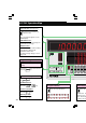
LS-7001 Operation Map Select the area (See page 3-4) Press the Up or Down key to select the area. AREA The selected area appears on the AREA display. POSITION monitor The POSITION monitor is lit according to the position and size of the target. FOCUS monitor The FOCUS monitor is lit according to the distance between the transmitter and receiver. To make lit range changes, refer to page 4-14.
OUT 1 Tolerance setting (See page 4-50) OUT 2 HI Reference value mode GO LO Upper limit setting: Press the HI key. Reference value setting: Press the GO key. Lower limit setting: Press the LO key. TIM TION HI Threshold setting GO US HI value setting: Press the HI key. HH value setting: Press the HI key 2X. LO value setting: Press the LO key. LL value setting: Press the LO key 2X.
Contents Safety Precautions .............................................................................................................. i Precautions for CE Markings ........................................................................................... iv About this Manual .............................................................................................................. v Page Configuration and Symbols ....................................................................................
Chapter 4 Function Settings Flow of Program Settings ............................................................................................... 4-2 Default Values and Possible Setting Ranges ............................................................... 4-4 Copying Program Setting Details and Initialization ..................................................... 4-6 Area Settings ...................................................................................................................
Chapter 6 I/O Terminals Nomenclature and Functions of I/O Terminals ............................................................. 6-2 Terminal Block .............................................................................................................. 6-2 Connector I/O ............................................................................................................... 6-4 Functions ............................................................................................................
Chapter 1 Getting Started This section provides information on the configuration of the LS-7000 Series, precautions, and necessary preparations required before operating the LS-7000 Series. Familiarize yourself with this section before using the LS-7000 Series. Outline and Features of LS-7000 Series .............................. 1-2 System Applications ............................................................. 1-3 Package Contents ................................................................
Chapter 1 Getting Started Outline and Features of LS-7000 Series The LS-7000 Series is a high-speed, high-accuracy digital micrometer used for the dimensional measurement of objects without coming into contact with the objects. It is such a versatile model that it has a wide range of applications including in-line measurement and offline measurement.
Chapter 1 Getting Started System Applications The LS-7000 Series has a wide range of applications when used in combination with commercially available peripheral devices. Printer The results of measurement are printed. PC Control values or measuring values are retrieved over RS232C. 1 Programmable Logic Controller Control output and measured values are retrieved and programs for measurement timing control are changed.
Chapter 1 Getting Started Package Checks Check that nothing is missing from the LS-7000 Series package before use.
Chapter 1 Getting Started LS-7070 Measuring Head Allen-head bolt (Six, M4 x 50 with a washer) 1 Allen-head bolt (Four, M5 x 20) LS-C✱✱A Extension Cable (Cable between the controller and measuring head) LS-C3A: 3-m cable ✱✱... LS-C10A: 10-m cable ✱✱... LS-C30A: 30-m cable Up to two cables are connectable, provided that the total length of the cables does not exceed 40 m.
Chapter 1 Getting Started LS-S11 Stand Unit Base Unit 1 Screws (Four, M4 x 8) ❈ Keyence ships each package with utmost care and attention. If there should be any improper or damaged product, contact your Keyence representative.
Chapter 1 Getting Started Functions and Nomenclature The following section provides information on the functions and nomenclature of the controller and measuring head. 1 Controller Control Panel (Page 1-8, Control Panel) Controller (Rear Side) Connector I/O Used for signal I/O (Page 6-2, Section 6 I/O Pin) Modular Connector Used to connect the console connector or RS-232C cable connector.
Chapter 1 Getting Started ■ Control Panel 1 OUT 1 OUT 2 HI (1) GO (19) (20) LO TIM (3) AREA 1 2 HI (4) GO (5) (6) PROG (21) POSITION (2) (17) FOCUS LO ESC HOLD (16) ZERO (15) PRINT (7) FUNC ENT PROG No. AREA DISP LS-7000 (8) (10) (9) (11) (12) (1) Main display: (18) (13) (14) The measured value is displayed. Refer to Selection of Measured Value Display on page 3-2.
Chapter 1 Getting Started (14) Display selection key: (15) ZERO key: (16) HOLD key: (17) HI , GO , and LO keys: and keys: (18) (19) Output selection display: (20) Comparator result display: (21) Timing display: Press this key to select the main display or sub display when measuring. (Page 3-2, Switching Display Screen) Press this key to select the auto zero function. (Page 3-6, Automatic Zero Function) Press this key to select the hold function.
Chapter 1 Getting Started LS-7030 Multi-purpose Mounting Holes A fixture for targets can be attached. 1 Cover Glass Transmitter (T Head) Emits light for measurement. TR Base Used to mount the transmitter and receiver. Receiver (R Head) Receives light from the transmitter. TR Cables Used to connect the transmitter and receiver. Mounting Holes Used to mount the measuring head. Extension Cable Connected to the controller. LS-7070 Multi-purpose Mounting Holes A fixture for targets can be attached.
Chapter 1 Getting Started Mounting and Connection Mount the measuring head and the controller, and connect them with the cables. 1 ■ Mounting the Measuring Head The measuring head can be mounted with or without the TR base employed, according to the type of targets and operating environment. The following section provides information on how to mount the measuring head with or without the TR base employed, along with mounting conditions required.
Chapter 1 Getting Started ■ With TR Base The transmitter and receiver are mounted to the TR base at the time of shipment. This section provides how to install the transmitter and receiver (LS-7030 in this case) that are mounted on the TR base.LS-7010 and LS-7070 can also be installed in the same way. 1 Use the four, M4x20 Allen-head bolts, which are provided with the package, to mount the TR base. To mount the TR base with the bolts on the surface of the TR base, use the mounting holes on the surface.
Chapter 1 Getting Started Use the 5-mm-deep M4 bottom mounting holes of the transmitter and receiver as shown in the illustration. 1 Mounting the Controller ■ Mounting Restrictions Be aware of the following items when mounting the controller. CAUTION Note: • Do not install the controller upside down. • Do not block the ventilation louver. Otherwise, the interior heat may cause the controller to malfunction.
Chapter 1 Getting Started ■ Mounting to Panel The controller can be mounted to control panels with the mounting brackets provided with the package. Arrange the following panel mounting dimensions. 1 207 169 124 +1 0 +1 0 200 Unit: mm 1 Mount the controller from the front side of the panel. 2 Attach resin caps to the mounting brackets. 3 Insert the mounting brackets to the four mounting holes on the side of the controller respectively.
Chapter 1 Getting Started 4 Secure the mounting brackets with a Phillips screwdriver. 1 CAUTION • Tighten the mounting screws to a maximum torque of 0.4 Nm. Do not tighten up the mounting screws excessively, otherwise the panel or controller casing may be deformed. • Do not remove the gasket, otherwise the controller will not satisfy IP64 conditions.
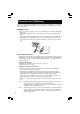
Chapter 1 Getting Started 3 Connect the cable between the controller and measuring head. If only a single measuring head is used, connect the cable to the HEAD1 connector. 1 Cable between controller and measuring head 4 Connect the power supply cable of the AC power supply stand to the controller. 5 Mount the stand unit to the base unit. Mount the stand unit with the two screws provided with the package. (2) Lean the stand unit in the direction indicated by the arrow.
Chapter 1 Getting Started Tips The back of the AC power supply stand has legs. Erect the legs and use the AC power supply stand if required. 1 Connection Connect the measuring head, controller, and power supply with the cables. CAUTION Do not supply power to the controller while connecting the cables. If the AC power supply stand is used, turn off the AC power supply stand while connecting the cables.
Chapter 1 Getting Started ■ Transmitter and Receiver Connect the cables of the transmitter and receiver respectively. Connect both connectors so that the notched part of each connector will coincide with each other in position. 1 Transmitter side Receiver side ■ Measuring Head and Controller Connect the cables of the controller and the measuring head. Connect both connectors so that the notched part of each connector will coincide with each other in position.
Chapter 1 Getting Started Supply Stand On and Off This section provides information on how to turn the AC power supply stand on and off. 1 ■ Turning Power On 1 Turn on the POWER switch on the rear panel of the AC power supply stand. ■ Turning Power Off 1 Turn off the POWER switch on the rear panel of the AC power supply stand.
Chapter 1 Getting Started Setting Overview The LS-7000 Series is in measurement operation according to a variety of settings. The following section provides information on each mode in detail and how to switch between modes. 1 Power On Tolerance Setting RUN Mode OUT 1 OUT 1 OUT 2 HI GO TIM LO AREA 1 2 POSITION TIM HI GO HI FOCUS HI GO LO OUT 2 HI GO LO LO GO Measures according to the set program.
Chapter 1 Getting Started Resetting to Initial Status The following section provides information on how to reset all the programs and environment settings to factory-set values. 1 Refer to 5-2 Resetting All Programs on page 5-5 if the resetting of only the programs to factory-set values is required. Tips 1 Turn on the LS-7000 Series with the ZERO key pressed. HOLD ZERO AREA This display will appear when the LS7000 Series is turned ON.
Chapter 1 Getting Started MEMO 1 1-22
Chapter 2 Easy Setting Guide The LS-7000 Series is used for a variety of measurement applications if the LS-7000 Series is set properly. This section provides information on targets and settings for typical applications respectively. Measurement of Outer Diameter and Width (with Single Measuring Head) ............................................. 2-2 Measurement of Outer Diameter and Width (with Two Measuring Heads) ...............................................
Chapter 2 Easy Setting Guide Measurement of Outer Diameter and Width (with Single Measuring Head) In the following example, a single measuring head is used to measure the outer diameter of an object in one direction. The result of measurement is displayed as OUT1. 2 D Measures the outer diameter in one direction. ■ Set Values Set item Area setting Set value AREA 1 AREA Calibration Head 1 DIA Make settings if required.
Chapter 2 Easy Setting Guide Measurement of Outer Diameter and Width (with Two Measuring Heads) In the following example, two measuring heads are used to measure the average outer diameter of an object in two directions. The measurement of the object in two directions ensures high accuracy. The result of measurement is displayed as OUT1. 2 Y X D= X+Y 2 Measures the outer diameter in two directions.
Chapter 2 Easy Setting Guide Measurement of Outer Diameter and Width (with Two Measuring Heads for Larger Objects) A sheet cannot be located in the measuring area of a single measuring head if the width or diameter of the sheet is excessively large. In that case, the sheet can be measured with two measuring heads as shown below with the automatic zero function and the master workpiece used. The result of output is displayed as OUT1.
Chapter 2 Easy Setting Guide Measurement of Inner Diameter and Clearance In the following example, the inner diameter of the workpiece is measured while the workpiece moves. The maximum value measured is taken as the inner diameter of the workpiece. The result of output is displayed as OUT1. 2 ■ Set Values Set value Set item AREA 1 Area setting AREA Calibration Head 1 SEG (001-E, 002-E) Operation Averaging Offset OUT 2 A1: 1.0 A2: OFF Select the value according to the line speed.
Chapter 2 Easy Setting Guide Measurement of Outer Diameter and Eccentricity In the following example, the outer diameter and eccentricity of the roller is measured while the roller moves. The outer diameter is displayed as OUT1, and the eccentricity is displayed as OUT2. 2 Eccentricity Outer diameter ■ Set Values Set item Area setting Set value AREA 2 AREA 1 AREA Calibration Head 1 DIA Head 1 T-EDGE Make settings if required. OUT 1 Output setting Operation Averaging A1: 1.0 A2: OFF A2: 1.
Chapter 2 Easy Setting Guide Measurement of Movement and Positioning In the following example, the movement or position of the workpiece is measured. The result of output is displayed as OUT1. 2 ■ Set Values Set value Set item AREA 1 Area setting AREA Calibration (000-E, 002-E) Operation Averaging Offset OUT 2 A1: 1.0 A2: OFF Select the value according to the line speed Measuring mode Normal Tolerance setting No settings are required Make settings if required.
Chapter 2 Easy Setting Guide Measurement of Pitch The single pitch of connectors pins or IC pins is measured by the LS-7000 Series. Furthermore, multiple pitch of pins is measured with the program function or RS-232C interface used. 2 The center pitches of the two portions are measured at a time. ■ Set Values Set value Set item AREA 1 Area setting AREA Calibration AREA 2 Head 1 SEG Head 1 SEG (002-P, 004-P) (004-P, 006-P) Make settings if required.
Chapter 3 Operation Control This section provides information on setting control items on the control panel while the LS-7000 Series is in measurement operation. Selection of Measured Value Display ......................... Area Monitor ................................................................ Hold Function .............................................................. Automatic Zero Function ............................................. Panel Lock Function ..........................................
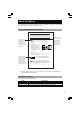
Chapter 3 Operation Control Selection of Measured Value Display Displayed values on the main and sub displays can be switched. The main display can display the measured results of OUT1 (or OUT2) and the sub display can display tolerance comparator set values or measured values simultaneously. Four display types can be selected in two tolerance modes (i.e., the reference value mode and threshold mode). Refer to Option settings on page 4-54 for the selection of the reference value mode or threshold mode.
Chapter 3 Operation Control ■ Tolerance Mode with Threshold Out 1 is lit. Out 1 measured value is displayed. OUT 1 OUT 2 HI GO LO TIM AREA 1 2 POSITION Out 1 HI value is displayed. HI GO FOCUS Out 1 LO value is displayed. LO DISP DISP 3 Out 2 is lit. Out 2 measured value is displayed. OUT 1 OUT 2 HI GO LO TIM AREA 1 2 POSITION Out 2 HI value is displayed. HI GO FOCUS Out 2 LO value is displayed. LO DISP DISP Out 1 is lit. Out 1 measured value is displayed.
Chapter 3 Operation Control Area Monitor The area monitor display can be used to confirm the insertion positions of the targets in AREA1 or AREA2 to be selected. Press the AREA key on the control panel and select the area. The following items will be displayed when the area is selected. 3 HOLD ZERO AREA DISP The selected area number is lit. AREA 1 2 POSITION POSITION Monitor The POSITION monitor is lit according to the position and size of the target in the CCD scanning range.
Chapter 3 Operation Control Hold Function Measured values can be held and displayed. Furthermore, measuring mode combinations allow the measurement of a variety of values, such as maximum and minimum values. The types of measured values held vary with the measuring mode. Refer to Measuring Mode on page 4-33 for details. Measured values are held and displayed through the following functional components.
Chapter 3 Operation Control Automatic Zero Function The automatic zero function sets measured values to zero (0.00000) instantly. This function is convenient for zero-point calibration for a variety of targets. Furthermore, master calibration is possible by using this function in combination with the offset function. Note: Tips 3 This function will not be available while the controller is awaiting the result of measurement, during which the monitor will display “– – –. – – – –.
Chapter 3 Operation Control Panel Lock Function The panel lock function is used to lock the control panel so that no key input will be enabled. As a result, there will be no risk of making setting changes with careless key input. Panel Lock Types The following types of panel locks are possible with the PAN-LOC settings as environment settings. Refer to Panel Lock on page 5-13 for details. • Set the panel lock type to ALL: All keys will be locked.
Chapter 3 Operation Control Program Changes The following section provides information on how to call 16 programs saved in the LS7000 Series. Names and Number of Programs The selected program is displayed on the display monitor next to the [PROGRAM No.] key. It is possible to register 16 alphanumeric characters (i.e., 0 through 9 and A through F) for program numbers. Programs are selected through the following functional components.
Chapter 4 Function Settings The LS-7000 Series is available to the measurement of a variety of items by making setting changes. These settings can be registered as programs that can be used whenever required. This section provides information on the overview of program settings and setting methods. Flow of Program Settings ............................................ 4-2 Default Values and Possible Setting Ranges .............. 4-4 Copying Program Setting Details and Initialization .....
Chapter 4 Function Settings Flow of Program Settings The following section provides information on the types and flows of program settings available to the LS-7000 Series along with the relationship between the program settings and external I/O.
gs (See page 4-20) Optional) Chapter 4 Function Settings External I/O Output Settings (See page 4-28) Optional Settings Area calculation Averaging number ■ Offset (in combination with the automatic zero function) selection ■ ration alibration calibration ■ nitialization 4 ZERO TIMING Measuring Mode Settings RESET Output Settings ■ Analog output settings Scaling (Reference value/Threshold) Analog update mode Output waiting voltage Analog output ■ Comparator output settings Comparator output
Chapter 4 Function Settings Default Values and Possible Setting Ranges The following programs settings are made by default. Items in parentheses indicate what is displayed on the monitor. ■ Area Settings (AREA) (Page 4-7) Item Default Measuring head selection (HEAD No.
Chapter 4 Function Settings ■ Output Settings (OUTPUT) (Page 4-28) Item Area calculation (CALC) Averaging number (AVERAGE) Default OUT1: A1 1.0 A2 OFF OUT2: A1 OFF A2 1.0 512 Measuring mode (MEA-MODE) Normal Offset (OFFSET) Scaling at +10 V (A-OUT +10) Threshold (TOL) Scaling at –10 V (A-OUT –10) Reference Scaling (A-UNIT) value (DEV) Analog output setting: Analog update mode (A-SET) 0.00000 +30.00000 Possible setting range OFF, 1.0, 0.5, –1.0, –0.
Chapter 4 Function Settings Copying Program Setting Details and Initialization The LS-7000 Series can be initialized so that the details of programs will return to ones set by default. Furthermore, the LS-7000 Series has a function making it possible to copy the details of any program to different programs. Copying Program Setting Details The details of any program can be copied to different programs by using the P-COPY item as an environment setting. Refer to Copying Programs on page 5-5 for details.
Chapter 4 Function Settings Area Settings Area settings are used to determine the measurements taken from a variety of objects placed in the beam. The LS-7000 Series can use up to two measuring heads to set two measurements (AREA1 and AREA2) for simultaneous measurements. Area Settings Area settings include the following items. • Area: Select the measuring head number together with the DIA, T-EDGE, B-EDGE, or SEG mode. • Focus monitor: A function to check whether the target is within the measuring range.
Chapter 4 Function Settings Flow of Area Setting Display OUT 1 OUT 2 HI GO LO TIM AREA 1 2 POSITION HI GO FOCUS PROG This part changes. LO ESC HOLD PRINT FUNC ZERO ENT PROG No.
Chapter 4 Function Settings Area Selection Area When a target is located in the measuring area as shown below, the light into the receiver is partly obstructed, thus creating a shadow. The contour of the shadow is called “edge.” The area is surrounded by the edge line. The LS-7000 Series can measure objects with area designation or edge designation. Area designation is possible in DIA, T-EDGE, or B-EDGE mode. Edge designation is possible in SEG mode.
Chapter 4 Function Settings ■ T-EDGE (Top Edge)/B-EDGE (Bottom Edge) Select either of these settings for the gap measurement or positioning of rollers. 4 When the LS-7000 Series is in T-EDGE measurement operation, it measures the width of the bright portion between the top of the measuring head and the first shadow in the measuring area.
Chapter 4 Function Settings E (Edge) Mode The LS-7000 Series measures objects based on the edges in this mode. 4 Set the edge numbers to positive values beginning with the top of the measuring head. The following example shows positive edge numbers and measuring portions.
Chapter 4 Function Settings P (Pitch) Mode The LS-7000 Series measures objects based on the middle point between the edges of the objects in this mode. In this example as shown, five P-mode edges exist, based on which the LS-7000 measures the center pitch of the target in the measuring area. Center pitch: The space between 2P and 4P 4 Top 1E 2E Target center pitch 1P 2P 3E 4E 5E Edge 0 Edge 0 refers to a method of measurement, in which the center of the optical axis is used as an origin.
Chapter 4 Function Settings screen. AREA 1 2 POSITION FOCUS PROG ESC H PRINT FUNC Z ENT PROG No. AREA DISP HI Measuring head No. 1 HI DIA (Diameter) HI Measuring head No. 2 HI T-EDGE (Top edge) HI B-EDGE (Bottom edge) GO SEG (Segment) LO 4 SEG (Segment) Setting Input the start edge (pitch) number. The value must be smaller than the end edge (pitch number). HI The setting part flashes. GO Select the E or P mode as desired. LO Input the end edge (pitch) number.
Chapter 4 Function Settings The input value is entered and the value in the next line flashes. (3) Input the end edge (pitch) number. 4 Press the ENT key. The input value is entered and the area display appears again. Focus Monitor The focus monitor is a function that makes it possible to check whether the target is located within the range where the highest precision measurement of the target is ensured. The focus monitor range is the distance between the receiver and target in the measuring area.
Chapter 4 Function Settings Area Check Set the total number of edges to be measured. If the number of edges detected does not coincide with the set value, the measured value will be invalidated. This function makes it possible to prevent the measurement of abnormal values that may result if dust or oil is stuck on the measuring head. The monitor will display the following data if the measured value is invalidated.
Chapter 4 Function Settings Difference Check If there is a radical change between measured values, the change will be detected and output. Setting Range • Difference average: 1 to 16 times • Difference value: 1 to 9999 μm Note: The results of difference checks will be output externally, provided that DIFF function output settings are made properly in advance. Refer to Function Output Selection on page 4-19 for details. The result output of a difference check is a 26.
Chapter 4 Function Settings 6 Press the ENT key after the value is set. The input value is entered and the area display appears again. Function Output Selection Select either Focus, Area, or Difference to be output from the output terminal block on the rear panel. Setting Range Any one of the following items is selectable for output. Refer to Section 6 I/O Terminals on page 6-1 for the FUNCTION output terminals in details.
Chapter 4 Function Settings Change of Edge Detection Threshold The following section provides information on how to make threshold changes for the measurement of highly transparent objects.
Chapter 4 Function Settings ■ Setting method 1 Select the area to be set and press the ENT HI key. 2 Press the GO FUNC key five times. LO 3 Press the or key and set the threshold. AREA 1 2 POSITION Threshold G FOCUS PROG The setting part flashes. L ESC 4 H PRINT FUNC ZE ENT PROG No. AREA DISP Press these keys to set the value. 4 Press the ENT key. The input value is entered and the area display appears again.
Chapter 4 Function Settings Calibration Settings The measured value of a target may have a subtle error due to the surface condition and angle of the target. Calibration settings correct for this error. It is possible to make calibration settings for each area independently. ■ Types of Calibration Settings Select the type of calibration from the following ones in advance. Refer to Calibration Type Selection on page 4-23.
Chapter 4 Function Settings ■ Procedure for Calibration Settings Make calibration settings while monitoring the sub display. 1 Press the PROG key. PROG ESC PRINT FUNC ENT 2 Press the FUNC key four times. The “Calib” display appears.
Chapter 4 Function Settings Flow of Calibration Setting Display OUT 1 OUT 2 HI GO LO TIM AREA 1 2 POSITION HI GO FOCUS PROG This part changes. LO ESC HOLD PRINT FUNC ZERO ENT PROG No.
Chapter 4 Function Settings Calibration Type Selection The following section provides information on how to set the calibration type for each area. 1 Press the ENT key for calibration HI setting. 2 Press the FUNC key twice. Press the FUNC key three times to set the AREA2 calibration type. 3 Press the or key and select the AREA1 calibration type. GO LO AREA 1 2 POSITION G FOCUS The following items are displayed for setting. PROG H PRINT FUNC ZE ENT PROG No.
Chapter 4 Function Settings 1 Press the ENT key for calibration setting. The AREA1 calibration display appears. Press the FUNC key to make AREA2 settings. HI GO LO 2 Input T1-A Value. Indicates that AREA1 is selected. A POSITION HI GO G 4 Press this key to set the value to a positive or negative one. FOCUS LO ESC HOLD Indicates that the T1-A value is displayed. The input part flashes. PRINT C ZERO ENT PROG No. AREA DISP Press these keys to set the value. 3 Press the ENT key.
Chapter 4 Function Settings Two-point Calibration Settings Make two-point calibration settings as explained below. Setting Range Two-point calibration requires two types of master workpieces that are different to each other in size. If the master workpieces are target 1 (T1) and target 2 (T2) respectively, make settings so that the following conditions will be satisfied. T1 < T2 Furthermore, set the calibration span between 0.5 and 2.0.
Chapter 4 Function Settings One-point Calibration Settings Make one-point calibration settings as explained below. Note: In the case of one-point calibration, the number of averaging measurements is fixed at 4,096 times. 1 Press the ENT key for calibration setting. The AREA1 calibration display appears. HI GO LO 2 Set the master workpiece, monitor the measured value, and input the T1 value. 4 Indicates that AREA1 is selected. Indicates that AREA1 is selected.
Chapter 4 Function Settings Initializing AREA1 Calibration Value (1) Press the or key. “Reset” appears on the screen. AREA 1 2 POSITION G (2) Confirm the area to be initialized and press the ENT key. FOCUS PROG L ESC H PRINT FUNC ZE ENT PROG No. AREA DISP Initialization of AREA2 Calibration Value (1) Press the FUNC key. The AREA2 settings appear. AREA 1 2 POSITION 4 G FOCUS PROG L ESC H PRINT FUNC ZE ENT PROG No. or key. (2) Press the “Reset” appears on the screen.
Chapter 4 Function Settings Output Settings Values measured in AREA1 and AREA2 can be processed in a variety of ways and output as OUT1 and OUT2 signals. This section provides information on the details and methods of output settings. Possible Output Settings The following output settings are possible. • Area calculation: The measured values of two-area points specified by area settings are used for calculation processing. • Number of averaging measurements: Set the number of measuring times.
Chapter 4 Function Settings Flow of Output Setting Display OUT 1 OUT 2 HI GO LO TIM AREA 1 2 POSITION HI This part changes. GO FOCUS PROG LO ESC HOLD PRINT FUNC ZERO ENT PROG No.
Chapter 4 Function Settings Area Calculation The measured values from the two memory areas are used for calculation processing. Setting Range Select the coefficient from the following. OFF (No coefficient will be multiplied and the value will be 0), 1.0, 0.5, -1.0, or -0.5 ■ Examples of Area Calculation By multiplying the measured values with the coefficient selected, automatic size calculation will be obtained. Set the coefficient as explained below to obtain the desired output value.
Chapter 4 Function Settings 2 Press the or key and set the coefficient for AREA1. AREA 1 2 POSITION The setting part flashes. AREA1 setting G FOCUS PROG L ESC H PRINT FUNC ZE ENT PROG No. AREA DISP 3 Press the ENT key. The input value is entered and the AREA2 value flashes. 4 Press the 5 Press the or key and set the coefficient for AREA2. ENT key. The input item is entered and the output setting display appears again.
Chapter 4 Function Settings Example: If the averaging number is eight, the LS-7000 Series will output the data as shown below. Internal data (2,400 samples/s) 1 2 3 4 5 6 7 8 9 10 11 12 13 14 Data samples 1 through 8 are averaged, and data A is output. Measurement averaging time Measurement averaging time Data samples 3 through 10 are averaged, and data B is output. Measurement averaging time A Output data B C Data samples 5 through 12 are averaged, and data C is output.
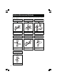
Chapter 4 Function Settings Measuring mode The Measuring mode allows the LS-7000 Series to capture and hold measured values. Setting Range The LS-7000 Series has 11 types of Measuring modes. Refer to the following information for the outline of each mode. Normal The measured value is displayed and output as it occurs. Bottom Hold The minimum value during the period specified is displayed and output. Average Hold The average value during the period specified is displayed and output.
Chapter 4 Function Settings Application Example of Measuring modes Select the measurement mode according to the type of target and measuring condition. The following applications are typical examples of measurement in a variety of Measuring modes.
Chapter 4 Function Settings Timing Chart The following table lists timing charts for respective measuring modes.
Chapter 4 Function Settings ■ Peak Hold • Peak hold: The maximum value during the sampling period specified by external timing input is displayed and output as shown below. • Bottom hold: The minimum value during the sampling period specified is displayed and output. • Peak-to-peak hold: The maximum-to-minimum value during the period specified is displayed and output. • Average hold: The average value during the sampling period specified is displayed and output.
Chapter 4 Function Settings ■ Auto Peak Hold • Auto peak hold: The maximum value measured by the LS-7000 Series in continuous measurement operation is displayed and output. • Auto bottom hold: The minimum value measured by the LS-7000 Series in continuous measurement operation is displayed and output. • Auto peak-to-peak hold: The maximum-to-minimum value measured by the LS-7000 Series in continuous measurement operation is displayed and output .
Chapter 4 Function Settings ■ Sample Hold 1 The instantaneous value at the time specified by external timing input is displayed, and the value is output as shown below.
Chapter 4 Function Settings ■ Sample Hold 2 The value measured during the period specified by external timing input is displayed, and the value is output as shown below.
Chapter 4 Function Settings ■ Self-timing Hold The LS-7000 Series in self-timing hold operation will detect targets automatically with no external timing input. Then the measured value is displayed and output.
Chapter 4 Function Settings ● Self-timing Hold and Area Settings The LS-7000 Series in self-timing hold operation will detect a target when the target is within the optical axis. Then the LS-7000 Series will start sampling after a certain period (i.e., a self-timing period) elapses. Therefore, the target may enter the measuring area from any direction as shown below.
Chapter 4 Function Settings Setting Method 1 Press the ENT key when the output setting is displayed. 2 Press the HI key twice. FUNC GO LO 3 Press the or measuring mode. key and set the POSITION AREA 1 2 G FOCUS 4 PROG L ESC H PRINT FUNC ZE ENT PROG No. AREA DISP The following displayed items can be selected.
Chapter 4 Function Settings 4 Press the ENT key. The input item is entered and the output setting display appears again. Offset An offset value is a desired value that can be added to or subtracted from measured values. If the offset value is set, it is possible to display the offset value immediately on the screen by using the auto zero function. Setting Range The range can be set between –99.99999 and 99.99999 mm. This range varies with the display unit or minimum display unit setting.
Chapter 4 Function Settings Analog Output Settings The LS-7000 Series has analog voltage output according to the measured value. The range of analog voltage output is between –10 and +10 V. Setting Range The following analog output settings are available. • Scaling (reference value): In reference value mode (LIMITS), the deviation is output as a positive or negative voltage based on the reference value of 0 V.
Chapter 4 Function Settings The following table shows the relationship of scaling values along with their output ranges and resolutions. Scaling value [μm/V] Output range 1 ±10μm Resolution (❈) 0.01μm 2 ±20μm 0.01μm 5 ±50μm 0.02μm 10 ±100μm 0.04μm 20 ±200μm 0.08μm 50 ±500μm 0.2μm 100 ±1mm 0.4μm 200 ±2mm 0.
Chapter 4 Function Settings Setting Method 1 Press the ENT key when the output setting is displayed. 2 Press the FUNC HI key four times. GO LO 3 Press the or key and set the +10 V value. A Indicates +10 V value. POSITION HI 4 GO G Press this key to a positive or negative one. FOCUS LO ESC HOLD The selectable part flashes. PRINT C ZERO ENT PROG No. AREA DISP Press these keys to set the value. 4 Press the ENT key.
Chapter 4 Function Settings 3 Press the or key and set the analog update mode. 4 Press the AREA 1 2 POSITION G key. The input item is entered and the output setting display appears again. ENT FOCUS PROG L ESC H PRINT FUNC ZE ENT PROG No. AREA DISP ■ Output Waiting Voltage Take the following steps to set the voltage to be output when the display shows “- - - - - - - -.” 1 Press the ENT key when the output setting is displayed. 2 Press the FUNC HI key six times.
Chapter 4 Function Settings ■ Strobe Output Time Take the following steps to set the ON-time of strobe output. 1 Press the ENT key when the output setting is displayed. 2 Press the FUNC HI key seven times. GO LO 3 Press the or key and set the output time. 4 Press the POSITION G key. The input item is entered and the output setting display appears again. 4 AREA 1 2 ENT FOCUS PROG L ESC H PRINT FUNC ZE ENT PROG No.
Chapter 4 Function Settings ■ OFF-delay Time Take the following steps to set the OFF-delay time for comparator output. 1 Press the ENT key when the output setting is displayed. 2 Press the FUNC HI key nine times. GO LO 3 Press the or OFF-delay time. 4 Press the key and set the AREA 1 2 POSITION G key. The input item is entered and the output setting display appears again. ENT FOCUS PROG 4 L ESC H PRINT FUNC ZE ENT PROG No.
Chapter 4 Function Settings Tolerance (LIMIT) Settings The LS-7000 Series judges whether or not the measured values pass the criteria. The range of values used for judgment is called a tolerance. Tolerances can be set to OUT1 and OUT2 respectively. Types of Limits The following tolerance settings are possible. • Reference value Set the reference value and its upper and lower limits as deviation values. Measured values can be compared to three levels (i.e., HI, GO, and LO).
Chapter 4 Function Settings Limit Settings Take the following steps to make tolerance settings in reference value mode or threshold mode. Refer to Selection of Measured Value Display on page 3-2 to change OUT1 to OUT2 or vice versa. ■ Reference Value Mode 1 Press the key corresponding to the type of tolerance to be set. Press the HI key to set the upper limit, the GO key to set the reference value, and the LO key to set the lower limit. The corresponding tolerance item flashes.
Chapter 4 Function Settings 1 Press the key corresponding to the type of tolerance to be set. The corresponding tolerance item flashes. The following display flashes. Value HI GO LO Tolerance display HI set value HI GO HH set value HI GO LO set value GO LL set value GO LO 4 LO 2 Press the or key and set the A POSITION HI tolerance. GO 3 Press the flashing tolerance key again. The input value is entered. G FOCUS LO ESC HOLD PRINT C ZERO ENT PROG No.
Chapter 4 Function Settings Possible Setting Conditions ● Reference Value in Tolerance Mode Reference value + Lower limit hold value < Reference value + Upper limit hold value ● Threshold Value in Tolerance Mode Lower limit hold value < Upper limit hold value Note: If the input conditions are not satisfied, “Error-6” will appear on the main display. Reset the error status by pressing the ENT key or ESC key and make the settings again.
Chapter 4 Function Settings Option Settings Settings, such as display unit and I/O terminal mode, are available on the LS-7000 Series. Option Settings The following option settings are available. • Tolerance mode: Sets the tolerance mode to use either reference values or thresholds. • Timing mode: Sets the timing input terminals for OUT1 and OUT2 respectively. • Unit: Changes the display unit of measured values. • Minimum display unit: Changes the minimum display unit of measured values.
Chapter 4 Function Settings Flow of Option setting Display OUT 1 OUT 2 HI GO LO TIM AREA 1 2 POSITION HI GO FOCUS PROG This part changes. LO ESC HOLD PRINT FUNC ZERO ENT PROG No.
Chapter 4 Function Settings Tolerance Mode (LIMITS) Take the following steps to select the appropriate tolerance mode. Setting Range The following modes are selectable. • Reference value mode: Use this mode if there is a workpiece size change with the deviations (tolerances) unchanged. • Threshold mode: Specify the upper and lower limits in absolute values. 1 Press the ENT key when the option setting is displayed. HI GO LO 4 2 Press the or key and set the tolerance mode.
Chapter 4 Function Settings 1 Press the ENT key when the option setting is displayed. 2 Press the FUNC HI key. GO LO 3 Press the or key and set the AREA 1 2 timing input. POSITION G The following displayed items can be selected. FOCUS PROG L ESC H PRINT GO Asynchronous mode FUNC ZE ENT PROG No. GO AREA DISP Synchronous mode 4 4 Press the ENT key. The input item is entered and the option setting display appears again.
Chapter 4 Function Settings 3 Press the or key and set the display unit. The following displayed items can be selected. AREA 1 2 G FOCUS PROG GO mm μm GO inch GO mil L ESC H PRINT FUNC GO POSITION ZE ENT PROG No. AREA DISP To change the unit to UNIT3, press the key for 2 seconds when the UNIT2 is displayed. To change the unit to UNIT2, press the key for 2 seconds when the UNIT3 is displayed. 4 4 Press the ENT key.
Chapter 4 Function Settings 1 Press the ENT key when the option setting is displayed. 2 Press the FUNC HI key three times. GO LO 3 Press the or key and set the display unit. 4 Press the AREA 1 2 POSITION G key. The input item is entered and the option setting display appears again. ENT FOCUS PROG L ESC H PRINT FUNC ZE ENT PROG No. AREA DISP 4 I/O Mode The mode of the I/O connector on the rear panel of the controller can be changed.
Chapter 4 Function Settings Units, Default Minimum Values, and Setting Ranges Minimum display unit Setting item Calibration setting T1-A/B • T2-A/B Threshold Offset Output setting A– +10V A– –10V Threshold mode HH Reference value mode Tolerance setting 4 0.00002mm 0.00005mm 0.0001mm 0.00001mm 0.02μm 0.05μm 0.1μm 0.
Chapter 4 Function Settings Minimum display unit Setting item Calibration setting T1-A/B • T2-A/B Threshold Offset Output setting 0.000001inch 0.00005inch 0.0001inch 0.0000005inch 0.02mil 0.05mil 0.1mil 0.01mil Default value Setting range Default value Setting range Default value Setting range Default value Setting range A– +10V A– –10V Threshold mode HH Reference value mode Tolerance setting HI LO LL H-LMT L-LMT STANDARD UPPER LOWER H-LMT L-LMT 0.0000000inch 0.0000mil +0.3000000inch +300.
Chapter 4 Function Settings MEMO 4 4-62
Chapter 5 Environment Settings This section provides information on environment settings that include RS-232C interface settings along with basic operation settings and changes. Possible Environment Settings .................................... 5-2 Details of Environment Settings ..................................
Chapter 5 Environment Settings Possible Environment Settings The following environment settings are possible. • Program: Program setting changes, program copying, and setting initialization. • RS-232C: Baud rate, parity, stop bit, data length, data mode, and data transmission mode of the RS-232C interface. • Head: LED inspection function and mutual interference prevention function. • Beep: Turn the key buzzer ON or OFF. • Panel lock: Select which keys are locked.
Chapter 5 Environment Settings ■ Head (See page 5-10) Item Setting range Default LED inspection function (L-INSPCT) (–) HEAD1, HEAD2 (Connected head number) Mutual interference prevention function (H-SYNC) OFF OFF, ON ■ Beep (See page 5-12) Item Setting range Default Buzzer ON/OFF switch (BEEP) ON OFF, ON ■ Panel Lock (See page 5-13) Item Setting range Default Panel lock function (PAN-LOC) ALL 5 ALL, PART Changing Environment Settings Make changes to the environment settings.
Chapter 5 Environment Settings Flow of Environment Setting Display OUT 1 OUT 2 HI GO LO TIM AREA 1 2 POSITION HI GO FOCUS PROG This part changes. LO ESC HOLD PRINT FUNC ZERO ENT PROG No.
Chapter 5 Environment Settings Details of Environment Settings This section provides information on environment setting items and setting methods. Program The LS-7000 Series ensures ease of program settings or changes. Possible Settings • Program Selection (P-SELECT): Select the program from the front panel or the rear terminals. • Copying Programs (P-COPY): Program can be copied to other programs. Furthermore, a selected program can be initialized.
Chapter 5 Environment Settings 1 Press the 2 Press the 3 Press the ENT key when the program display is on the screen. FUNC key. or key to select the number of the program to be copied. The selectable part flashes. 4 Press the ENT key. The input item is entered and the value in the next line flashes. 5 Press the or key to select the destination program number. The selectable part flashes. 6 Press the ENT key. The input item is entered and the program display appears again.
Chapter 5 Environment Settings RS-232C Take the following steps to make the communication settings for the RS-232C interface and relative settings for peripheral devices. Tips Communication settings for the RS-232C interface vary with the peripheral device to be connected or the type of output desired. For the details of RS232C, refer to Chapter 7 RS-232C on page 7-1. Setting Items The following items can be set.
Chapter 5 Environment Settings 3 Press the or key and select the parity. The following displayed items can be selected. GO None GO Even GO Odd 4 Press the ENT key. The input item is entered and the RS-232C display appears again. ■ Stop Bit 1 Press the 2 Press the 3 Press the 4 Press the ENT key when the RS-232C display is on the screen. FUNC key twice. or key and select the stop bit. ENT key. The input item is entered and the RS-232C display appears again.
Chapter 5 Environment Settings 3 Press the or key and select the data mode. The following displayed items can be selected. GO None GO PLC GO GO Printer 1 Printer 2 4 Press the ENT key. The input item is entered and the RS-232C display appears again. Note: Other set values change as shown below according to the selected data mode. Setting item Description NORMAL Only the item OFF is selectable in data transmission mode. PLC The following environment settings are fixed.
Chapter 5 Environment Settings Head Take the following steps to set the LED inspection function and mutual interference prevention function. Setting Item • LED inspection function: The intensity of the LED light source can be inspected. • Mutual interference prevention function: Prevents mutual interference that may result when two measuring heads are located at right angles. Measuring Head Settings 1 Press the FUNC key twice when the program display is on the screen.
Chapter 5 Environment Settings Check on Fluctuation of Light Intensity Due to Dirt or Dust To check the dispersion of the amount of light, record the status of the clean cover glass. OUT 1 OUT 2 HI The distribution of light has fluctuation. GO LO TIM AREA 1 2 POSITION HI GO FOCUS LO In the above case, refer to page 3 and clean the cover glass.
Chapter 5 Environment Settings ■ Mutual Interference Prevention Function This function prevents mutual interference that may result when two measuring heads are located at right angles. With the function used, the LED light sources are turned sequenced ON and OFF. Note: If the mutual interference prevention function is used, the following settings will change. • The sampling cycle of measurement will be set to 1,200 times per second.
Chapter 5 Environment Settings Panel Lock Take the following steps to specify the panel lock range when the panel lock function is set. Setting Range Set the following items. • All (ALL): All function keys are locked. • Part (PART): All function keys other than the display selection function keys (DISP and AREA keys), HOLD keys, and tolerance setting keys ( HI , GO , and LO keys) are locked. Tips Refer to page 3-7 for the panel lock function in detail.
Chapter 5 Environment Settings MEMO 5 5-14
Chapter 6 I/O Terminals This section provides information on I/O terminal specifications and timing charts. Nomenclature and Functions of I/O Terminals ............ 6-2 Timing Chart .............................................................
Chapter 6 I/O Terminals Nomenclature and Functions of I/O Terminals This section provides nomenclature and functions of the I/O terminals of the LS-7000 Series. Types of I/O Terminals The LS-7000 Series has three types of I/O terminals. Use them according to the function used and the environment.
Chapter 6 I/O Terminals I/O Signal Names and Descriptions The I/O terminals handle the following signals. Refer to Function on page 6-7 for the functions of the signals in detail. For the electrical specifications of signals, refer to the reference pages indicated in the table.
Chapter 6 I/O Terminals Connector I/O Connector I/O signals operate in either SUB mode or BCD. Refer to I/O Mode on page 459 for details. Applicable Connector Specifications HIROSE ELECTRIC’s HIF3B Series or equivalent ones Terminal number 1 21 2 22 3 23 4 24 5 25 6 26 7 27 8 28 9 29 10 30 11 31 12 32 6 13 33 14 34 15 35 16 36 17 37 18 38 19 39 20 40 ■ I/O Signal Names and Descriptions The connector I/O terminals handle the following signals.
Chapter 6 I/O Terminals SUB Mode Terminal number 1 21 2 22 3 23 4 24 5 25 6 26 7 27 8 28 9 29 10 30 11 31 12 32 13 33 14 34 15 35 16 36 17 37 18 38 19 39 20 40 Signal name COM2 (Not used) (Not used) (Not used) (Not used) (Not used) (Not used) (Not used) (Not used) (Not used) (Not used) (Not used) (Not used) (Not used) COM2 (Not used) (Not used) (Not used) (Not used) (Not used) (Not used) (Not used) (Not used) (Not used) (Not used) AREA2 FUNCTION OUT2 HH OUT2 HI OUT2 GO OUT2 LO OUT2 LL OUT2 WAITING OUT2 STR
Chapter 6 I/O Terminals BCD Mode Terminal number 1 21 2 22 3 23 4 24 5 25 6 26 7 27 8 28 9 29 10 30 11 31 12 6 32 13 33 14 34 15 35 16 36 17 37 18 38 19 39 20 40 Signal name COM2 BCD POLE BCD DIGIT 7 (8) BCD DIGIT 7 (4) BCD DIGIT 7 (2) BCD DIGIT 7 (1) BCD DIGIT 6 (8) BCD DIGIT 6 (4) BCD DIGIT 6 (2) BCD DIGIT 6 (1) BCD DIGIT 5 (8) BCD DIGIT 5 (4) BCD DIGIT 5 (2) BCD DIGIT 5 (1) COM2 BCD DIGIT 4 (8) BCD DIGIT 4 (4) BCD DIGIT 4 (2) BCD DIGIT 4 (1) BCD DIGIT 3 (8) BCD DIGIT 3 (4) BCD DIGIT 3 (2) BCD DIGIT 3
Chapter 6 I/O Terminals Functions The following section provides information on I/O signal functions. For the arrangement of each terminal, refer to pages 6-2 and 6-4. ■ Alarm Output Name ALARM Description Reference page Turns ON when an error is detected. (Normally closed) 6-3 ■ Comparator Output Name 5-level comparator output (HH, HI, GO, LO, LL) Description Turns ON according to the result of the preset tolerances. This output can be set to NO (normally open) or NC (normally closed) type.
Chapter 6 I/O Terminals The following table shows a list of program numbers and the status of the P1 terminal through the P4 terminal.
Chapter 6 I/O Terminals ■ BCD Output Name Description Reference page BCD POLE output BCD polarity output. OFF: Positive ON: Negative 6-6 BCD DIGIT output BCD numeric output for each digit. Negative logic (i.e., Turns ON (set to 1) when NPN open connector output is ON). Comparator waiting status (with "–" displayed for each digit): All digits set to B (1011) Overrange (with "F" displayed for each digit): All digits turn ON (1111). 6-6 BCD INDICATE OUT1/2 output Present OUT number turns ON.
Chapter 6 I/O Terminals ■ NPN Open Collector Output 2 Internal circuit +5V +5V 470Ω Output 10kΩ 10kΩ 10nF COM2 Max. applied voltage 30V Max. sink current 30mA Residual voltage 1 V max. Current leakage 0.1 mA max. 6 Internal circuit ■ Analog Voltage Output 100Ω Output range ±10.5V (measured data:±10V) Resolution 4mV Accuracy ±0.05% of F.S. Output 10nF 0V (Based on displayed value and FS of 20 V) Output impedance 100Ω Response delay time Approx. 0.
Chapter 6 I/O Terminals Timing Chart This section provides information on the timing charts of BCD output in a variety of measuring modes. ■ Normal, Auto Peak Hold, Auto Bottom Hold, and Auto Peak-to-peak Hold Refresh cycle ON Comparator output OFF ON WAITING output OFF ON BCD output OFF STROBE time ON STROBE output OFF TIMING input 0±0.1ms ON OFF Min 2.1ms Min2.1ms Min Min2.1ms Max2.5ms ON RESET/ZERO input OFF Max2.5ms 2.1ms Max2.5ms ON P1 input to P4 input OFF RESET Min Min 6.0ms time 6.
Chapter 6 I/O Terminals ■ Sample Hold 2 ON OFF ON WAITING output OFF ON BCD output OFF Comparator output 0±0.1ms ON STROBE output OFF Min Min2.1ms 2.1ms ON TIMING input OFF RESET/ZERO input STROBE time Max2.5ms ON OFF Sampling Min2.1ms Min2.1ms period Max2.5ms ON P1 input to P4 input OFF Min6.0ms Min 6.0ms Max 8.0ms • Triggered by the acknowledgment of timing input, the measured value will be determined with an elapse of the sampling period (i.e., reset time).
Chapter 6 I/O Terminals ■ BCD Output Switching Refresh cycle OUT1 Measured value OUT1 STROBE output ON OFF Refresh cycle OUT2 Measured value OUT2 STROBE output BCD SELECT input BCD DATA output BCD INDICATE output ON OFF ON OFF 0±0.1ms ON OFF ON OUT1 OFF ON OFF OUT1 OUT1 OUT2 Max2.1ms OUT2 OUT1 OUT1 Max2.1ms • BCD output can be set to OUT1 or OUT2 according to BCD SELECT input.
Chapter 6 I/O Terminals ■ Minimum Input Period Refer to the relevant timing charts for the delay time (response delay time) in response to input. Name TIMING/ZERO/RESET P1~P4 6 6-14 Specifications ON : 2.1ms OFF : 2.1ms ON : 6.0ms OFF : 6.
Chapter 7 RS-232C This section provides information on how to connect the LS7000 Series to external devices along with RS-232C communications functions used for the external control of the LS-7000. Specifications .............................................................. 7-2 Communication using Serial Commands .................... 7-4 Communication using an External Synchronous Trigger .......................................................................
Chapter 7 RS-232C Specifications The LS-7000 Series has RS-232C communications functions. The following section provides information on the RS-232C communications specifications of the LS-7000 Series and the outline of communications settings that vary with the connecting device. ■ Applicable Connector Specification Modular 8-pin plug connector ■ Pin Arrangement Pin number Signal name 1 (Not used) 2 SD(TXD) Description 8 — 7 6 Receives (inputs into itself) 5 4 data from external devices.
Chapter 7 RS-232C ■ RS-232C Connection Settings Make the following environment settings according to the connecting device. For details, go to the reference pages indicated in the table. Refer to page 5-7 for RS-232C environment setting details. External device Non-protocol communications with PCs Environment setting item D-MODE D-SEND NORMAL or PLC link units.
Chapter 7 RS-232C Communication using Serial Commands To enable the LS-7000 Series to transmit measured values or allow setting changes, connect a peripheral device, such as a PC or PLC link unit to the LS-7000 Series. Connecting to a PC/PLC Link Unit The following section provides information on how to connect PCs or PLC link units to the LS-7000 Series. Use the dedicated OP-35382 cable (with 9-pin D-sub connectors) or the OP-25253 (with 25-pin D-sub connectors) for connection.
Chapter 7 RS-232C Connecting to KV Series The following information provides information on how to connect Keyence’s KV-series Programmable Logic Controller to the LS-7000 Series. Use the dedicated OP-25254 to connect the KV to the LS-7000. Note: • The output of the LS-7000 Series under external synchronous control cannot be connected to printers. • Only the KV-300/Visual Series can transmit text data. The KV-10/80 series can not be used with this mode. Refer to page 7-23 for more details.
Chapter 7 RS-232C Outline of Command Formats When LS-7000 Series receives a command from the external device, the LS-7000 Series will respond to the received command and return a response to the external device. The following section provides information on respective command formats. Note: When you write a control program, check that the program will enable the external device to send the next command after the external device confirms the response from the LS-7000 Series.
Chapter 7 RS-232C Measurement Serial Commands The following section provides information on serial commands used for measurement control.
Chapter 7 RS-232C Commands in Detail The following section provides information on commands and responses that the LS-7000 Series returns when commands are correctly processed. For error responses, refer to Outline of Command Formats on page 7-6. Refer to Timing Chart on page 7-21 for response delays. ■ Measured Value Output The LS-7000 Series can output a measured value. The following types of measured value output are possible. • Measured value output: The measured value is output.
Chapter 7 RS-232C Peak Hold, Bottom Hold, Peak-to-peak Hold, Average Hold, or Sample Hold 1 Measuring mode Sampling period Sampling period Max Max Measured value Command Response U[] L[] U[] Measured value U[] L[] Measured value U[] In peak hold mode, the maximum value of the sampling period is returned as a measured value. When the LS-7000 Series receives command L (measured value output), the internal timing is triggered and the determined measured value will be returned.
Chapter 7 RS-232C ■ Timing ON Command This command turns timing input ON. With command H0 executed, the operation of the LS-7000 Series will be the same as that with SYNC set as a T-MODE environment setting item. H q cr LS Response H q cr Output number 0: OUT1+OUT2 1: OUT1 only 2: OUT2 only With command H1 or H2 executed, the operation of the LS-7000 Series will be the same as that with ASYNC set as a T-MODE environment setting item. ■ Timing OFF Command U q cr This command turns timing input OFF.
Chapter 7 RS-232C ■ Program Number Selection Command P W This command selects program numbers. The command will be enabled if PANEL is set as a P-SELECT environment setting item. v cr Program No. 0~9, A~F LS Response P W cr ■ Program Number Confirmation Command P R cr This command is used to confirm the program number that has been currently set. The command will be enabled if PANEL is set as a P-SELECT environment setting item.
Chapter 7 RS-232C Setup Serial Commands The following section provides information on command formats that are used to make setting changes.
Chapter 7 RS-232C ■ Numeric Setting Format ( m m m m m m m m Format) This format is a fixed length format consisting of a single mark character and seven numeric characters with no decimal used. The following format will be used for the corresponding measured value. Measured value Format 1.23450 + 0 1 2 3 4 5 0 Commands in Detail The following section provides information on commands and responses that the LS7000 Series returns when commands are correctly processed.
Chapter 7 RS-232C ■ Area Check This command makes area check ON/OFF settings and changes the number of edges. Command S D , A T , a , f f f cr Area number 1 : AREA 1 2 : AREA 2 LS Number of area check edges OFF : OFF 002~127 : Value specified with the area check function turned ON. Response S D , A T , a cr Area number ■ Level This command changes threshold level settings.
Chapter 7 RS-232C ■ Measuring Mode This command changes measuring mode settings. Measuring mode 00 : NORMAL 04 : AV-HOLD 01 : P-HOLD 05 : A-P-HOLD 02 : B-HOLD 06 : A-B-HOLD 03 : D-HOLD 07 : A-D-HOLD Command S D LS , M E , h , k k cr Output number 1 : OUT1 2 : OUT2 Response S D , M E 08 : S-HOLD1 09 : S-HOLD2 10 : SELF-T , h cr ■ Self-timing Period If the measuring mode is set to self-timing hold, this command will change self-timing period settings.
Chapter 7 RS-232C Threshold Mode +10V set value Value setting format (See page 7-13) Command S D LS , A O , h , , A O , m m m m m m m m cr Output number 1 : OUT1 2 : OUT2 Response S D m m m m m m m m –10V set value Value setting format (See page 7-13) , h cr ■ Tolerance This command changes tolerance settings. The LS-7000 Series will return an error response if a command received is different in tolerance mode.
Chapter 7 RS-232C ● Threshold Mode HH Tolerance Value setting format (See page 7-13) Command S D LS , H H , h , Output number 1 : OUT1 2 : OUT2 Response S D , H H m m m m m m m m cr , h cr HI Tolerance Value setting format (See page 7-13) Command S D LS , H I , h , Output number 1 : OUT1 2 : OUT2 Response S D , H I m m m m m m m m cr , h cr LO Tolerance Value setting format (See page 7-13) Command S D LS , L O , h , , 7 Output number 1 : OUT1 2 : OUT2 Response S D m
Chapter 7 RS-232C ■ Hold Value Elimination ON/OFF This command turns the function of abnormal value elimination ON and OFF. Command S D , J O , h , Output number 1 : OUT1 2 : OUT2 LS Lower limit ON/OFF 1 : OFF 2 : ON w w cr Upper limit ON/OFF 1 : OFF 2 : ON Response S D , J O , h cr ■ Hold Value Elimination Set Value Change the set value of the function of abnormal value elimination.
Chapter 7 RS-232C Serial Commands to check the LS Settings The following section provides information on command formats used to check setting details.
Chapter 7 RS-232C Batch Commands It is possible to read the whole setting data of the LS-7000 Series and save the data on the PC. The saved data on the PC can be written to the controller as well. Use the program read and program write commands. These commands allow the following operations. • Reading and writing program settings (auto zero set values are included). • Reading and writing environment settings.
Chapter 7 RS-232C ■ Reading Environment Settings It is possible to read all environment settings in detail. Note: P-COPY, P-CLEAR, or L-INSPCT settings are not read with this command. Command S A cr LS Response S A , Data 0 Data 1 Data X Checksum Checksum Binary data Checksum range Data 0 through data X (X=87) The checksum need not be calculated for simple upload and download operations.
Chapter 7 RS-232C ASCII Table Rightmost 4 bits Leftmost 4 bits 0 1 2 3 4 5 6 7 7 7-22 0 1 2 3 4 5 6 7 8 9 A B C D E F N D S D U L O L E C H 1 S D T C X 2 E D T C X 3 E D O C T 4 E N N A Q K A S C Y K N B E E T L B B CA S N H E T M L SU F B V ES T C F F C R S O S I S P 0 1 2 3 4 5 6 7 8 9 A B C D E F G H I J K L M N O P Q R S T U V W X Y Z a b c d e f g h i j k \ l m n o p q r s t u v w x y z D T
Chapter 7 RS-232C Communication using an External Synchronous Trigger The following section provides information on how to obtain output from the RS-232C interface in synchronization with a timing input into the input terminal. This operation does not require ASCII commands. Therefore, use this function if the KV-10/80 Series (or the KV mode) is used only to retrieve measurements. This can also be used when connecting a data logger to the LS-7000 Series.
Chapter 7 RS-232C Timing Chart The following timing chart applies to timing input and RS-232C data output (the measuring mode is not set to sample hold 2 or self-timing hold.) TIMING input ON OFF RS-232C data output Measured value 3.5ms • If the measuring mode is set to normal, auto peak hold, auto bottom hold, or auto peak-to-peak hold, the measured value will be transmitted at the moment timing input is turned ON.
Chapter 8 Specifications This section provides the specifications, characteristics, and external dimensions of the LS-7000 Series. Specifications .............................................................. 8-2 Characteristics ............................................................ 8-4 Mode Specifications .................................................... 8-7 External Dimensions ...................................................
Chapter 8 Specifications Specifications Controller Model LS-7001 Number of connectable measuring heads 2 (interchangeable) Display type Display Minimum display unit Display range Main display 7-segment red LED (20.3 mm high) Sub display 7-segment red LED (9.9 mm high) x 3 0.1µm to 100µm (7 selectable levels), 0.0000005 to 0.000 inch (4 selectable levels) ±0.9999995 to ±999.9999 inch (varies with the minimum display units, inch/mil selectable), ±99.99999~±9999.
Chapter 8 Specifications Measuring Head Model LS-7010 LS-7030 LS-7070 Measuring range 0.04 to 6mm 0.3 to 30mm 0.5 to 65mm Minimum detectable object 0.04mm 0.3mm 0.5mm T-to-R distance 60±5mm 160±40mm 250±50mm GaN green LED Light source Approx. 69 mm CCD scanning range Approx. 7mm Approx. 33 mm Measurement position accuracy ±0.5µm (❈1) ±2µm (❈3) ±3µm (❈5) Repeating accuracy ±0.06µm (❈2) ±0.15µm (❈4) ±0.
Chapter 8 Specifications Characteristics Measurement Range and Accuracy LS-7010 40 30±5 81 (30) Transmitter Receiver 4 6 ±0.5μm ±1.5μm 2 4 LS-7030 Unit: mm 80 ± 40 35.
Chapter 8 Specifications 150 100±50 56 LS-7070 Receiver Transmitter ±3μm 20 65 40 ±6μm Unit: mm 30 Temperature Characteristics The following table shows typical examples of the temperature characteristics of the LS7000 Series. LS-7010 Temperature 0˚C 10˚C 20˚C 30˚C 40˚C 50˚C Drift 0.25 0.10 0.00 -0.05 -0.10 -0.15 Unit: μm 8 ❈ The above values are checked with a ø1 round bar located in the center of the measuring range at a reference temperature of 20˚C.
Chapter 8 Specifications Response Deley Time ■ Measurement Response Time The following table lists the response time between the moment the dimensional change of a target is detected and the measured result is obtained. Averaging times Measurement response time (ms) Measurement averaging time (ms) Refresh cycle (ms) Internal processing time (ms) 1 3.34 0.42 0.42 2.5 2 4.16 0.83 0.83 2.5 4 5.00 1.67 0.83 2.5 8 6.66 3.33 0.83 2.5 16 10.00 6.67 0.83 2.5 32 16.66 13.33 0.83 2.
Chapter 8 Specifications Mode Specifications ■ Measuring Mode Status Measured value display RS-232C Output Measuring Numeric display Comparator LED 5-level discrimination WAITING STROBE Analog output BCD ALARM FUNCTION Reception Response Comparator +All Comparator – – – – – – – OFF OFF ON OFF waiting O O digits: B waiting voltage Positiveside range over Value Negative side range over Reference value: HI Threshold: HH OFF Measured value Comparator output Comparator output OFF LO Reference value:
Chapter 8 Specifications External Dimensions It is possible to download CAD data on the external dimensions of the LS-7000 Series from KEYENCE’s URL (http://www.keyence.com/). ■ LS-7001 Controller Panel Mounting Dimensions (191) (Outer size of mounting bracket) 175 5 60 Panel thickness 1.2 to 4.0 207 Mounting screw 25 60 169 +1 0 Mounting bracket 130 +1 124 0 200 (65 ) ■ LS-7010 Measuring Head 4-ø4.5 through screw holes ø8 depth 4.
Chapter 8 Specifications ■ LS-7030 Measuring Head 4-M2.5 Depth: 3 max. 10 24 24 4-ø4.5 through screw holes ø8 depth 4.5 15 15 45 22±0.2 Measuring position 109 71.5 60 13.5 Front view of transmitter 6 55 55 Measuring range 126.5 30 4-M2.5 Depth: 3 max. 45 26 38 13.5 Front view of receiver 10 4-M4 Depth: 10 max. 60 71.5 35.5 5.5 5.5 3-ø5.5 (Mounting holes) 27 160 50 Cable length: 500 4-M4 Through 6 holes 26 26 135 27 214 6 Cable length: 200 19.5 3-ø5.
■ LS-S11 AC Power Supply Stand 171 196 60 (35 ) 14 178 43.5 148 216 201 (100 ) ■ Extension Cable LS-C**A Extension Cable (Cable between the controller and measuring head) 43 ø6.3 43 14.7 14 OP-42182/OP-42183 TR Cables 35 11.5 ø4.8 35.
Chapter 9 Troubleshooting This section provides information on troubleshooting and the contents of error messages. Troubleshooting Guide ................................................ 9-2 Error Messages ...........................................................
Chapter 9 Troubleshooting Troubleshooting Guide If the LS-7000 Series fails to operate, follow the inspection steps provided below. If the LS7000 Series does not operate normally after the inspection, contact your KEYENCE representative. Problem Inspection Remedy If 24 VDC is used Check that the power cable is Connect the power cable correctly. connected correctly. (See page 1-18) Check that the power supply is Use a power supply within the specified within the specified range. range.
Chapter 9 Troubleshooting Problem The measured value is not displayed. Inspection Remedy Check that the LED light source of Check the connection of the cable the transmitter is lit. between the transmitter and receiver. (See page 1-18) If the LED light source is still OFF, the LED light source needs a replacement. Contact your KEYENCE representative. Check that the measuring head is Connect the cable correctly. connected correctly.
Chapter 9 Troubleshooting Problem Inspection Remedy Check that the cover glass of the transmitter Remove the dirt and dust from the or receiver is free of dust and dirt. cover glass. (See page 3) Check that the target is within the Locate the target correctly in the measuring area. measuring area. (See page 8-4, 8-5) Check that the target is not leaned or Locate the target correctly in the shifted. measuring area. (See page 8-4, 8-5) The measured value displayed drifts.
Chapter 9 Troubleshooting Problem BCD output does not turn ON. Inspection Remedy Check that the I/O mode is correctly set. Select the BCD mode. (See page 459) Check that the LS-7000 Series is wired correctly. Check the output circuit and wiring. Connect the cables correctly. Check that the logic is correctly set. The LS-7000 Series has negative logic output. Check that the retrieval timing is correct. Use the strobe output and retrieve the input in correct timing.
Chapter 9 Troubleshooting Error Messages The following section explains error messages that will be displayed if the LS-7000 Series has errors while in operation. Display Description Measuring head error This error message will be displayed if the connector to the measuring head is changed, the measuring head is not connected correctly, or there is a failure in the measuring head or connection cable. Error-0 Remedy Check the wiring of the connection cable. Refer to the item ERROR-0 in this manual.
Appendix This section provides information on optional accessories and the index of this manual. List of Optional Accessories .................................. Appendix-2 Setting Record Sheet ............................................ Appendix-3 Environment Setting Record Sheet ....................... Appendix-5 Index ...............................................................
Appendix List of Optional Accessories Item Type Appearance Explanation TR Cable (1m) OP-42182 A 1-m extension cable used to connect the transmitter and receiver. Up to two TR cables are connectable, provided that the total length is 6 m or less. TR Cable (3m) OP-42183 A 3-m extension cable used to connect the transmitter and receiver. Up to two TR cables are connectable, provided that the total length is 6 m or less. I/O Cable (3m) OP-26505 A 3-m connector I/O cable.
Appendix Setting Record Sheet Use the following tables to record your setting details. ■ Area Settings Item Measuring head selection (HEAD No.
Appendix ■ Output Settings Item Default setting Setting detail OUT1 OUT2 OUT1 : A1 1.0 Area calculation (CALC) A2 OFF OUT2 : A1 OFF A2 1.0 Number of averaging times (AVE) 512 Measuring mode (MEA-MODE) NORMAL Offset (OFFSET) Scaling at 10 V Threshold (A-OUT+10) (TOL) Scaling at -10 V (A-OUT-10) Reference Scaling value (DEV) (A-UNIT) Analog output setting: Analog update mode (A-SET) 0.00000 +30.00000 0.
Appendix Environment Setting Record Sheet Use the following tables to record your environment setting details.
Appendix Index 1 One-point calibration ............................ 4-26 2 Two-point calibration ............................ 4-25 5 5-level comparator output ...................... 6-7 A Appendix A-TEST .................................................. 6-8 ALARM ................................................... 6-7 Alarm output ........................................... 6-7 Analog output setting .................. 4-29, 4-44 Analog scaling .............................
Appendix H HH ........................................................ 7-17 HH set value ......................................... 4-50 HI ................................................. 7-16, 7-17 HI set value .......................................... 4-50 Hold function .......................................... 3-5 HOLD-H ............................................... 7-18 HOLD-L ................................................ 7-18 Hold value elimination ..........................
Appendix S Sample hold 1 ............. 4-33, 4-38, 6-11, 7-9 Sample hold 2 ............. 4-33, 4-39, 6-12, 7-9 Scaling ................................................. 4-44 SEG (Segment) ........................... 4-10, 4-13 Self-timing hold .................. 4-33, 4-40, 6-12 Serial commands ............. 7-4,7-7,7-12,7-19 Serial commands to check the LS settings ................................................. 7-19 Setup serial commands ....................... 7-12 Self-timing hold ...................
WARRANTIES AND DISCLAIMERS (1) KEYENCE warrants the Products to be free of defects in materials and workmanship for a period of one (1) year from the date of shipment. If any models or samples were shown to Buyer, such models or samples were used merely to illustrate the general type and quality of the Products and not to represent that the Products would necessarily conform to said models or samples.
Copyright (c) 2012 KEYENCE CORPORATION. All rights reserved.