96M12426 Instruction Manual High-speed Laser Scan Micrometer LS-5000 Series
Safety Precautions This instruction manual describes the operation and function of the LS-5000 series. Read this manual carefully to ensure safe use and maximum performance from your LS-5000 series. The LS-5000 series uses a semiconductor laser as the light source. Before using the product, see “Laser Safety Precautions” on page 1 to learn the safe and correct method of using the LS-5000 series. Symbols The following symbols alert you to important messages. Be sure to read these messages carefully.
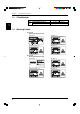
Checking the Contents of the Package The LS-5000 series includes the following items. Be sure to check that no item is missing or damaged. ■ • • • LS-5501 Package Built-in display type controller: 1 Instruction manual: 1 AC power cables: 2 1. ■ • • • • LS-5001 Package Separate type controller: 1 Instruction manual: 1 Communication cable (OP-26401 + OP-96368): 1 LS-VIEWER Software (3.
Contents Chapter 1 Laser Safety Precautions 1.1 1.2 1.3 1.4 1.5 1.6 Chapter 2 Before Using the LS-5000 Series 2.1 2.1.1 2.1.2 2.2 2.3 Chapter 3 Classification .......................................................................................... 2 Warning Labels ...................................................................................... 2 Label Location ........................................................................................ 3 Safety Consideration .......................
Chapter 6 Normal mode 6.1 6.2 6.3 6.4 Chapter 7 Normal Mode Screens ......................................................................... 24 Initial Screen ......................................................................................... 27 Setting Measuring Mode ..................................................................... 28 Setting Functions ................................................................................. 29 1 [HOLD] Hold Function ..................................
Chapter 8 RS-232C I/O 8.1 8.2 8.3 Chapter 9 Expansion I/O Board 9.1 9.1.1 9.1.2 9.1.3 Chapter 10 RS-232C Communication Protocol .................................................... 88 Remote Control Function .................................................................... 90 Command List ...................................................................................... 97 Control I/O Board ...............................................................................
Chapter 1 Laser Safety Precautions 1.1 Classification ........................................................................ 2 1.2 Warning Labels ..................................................................... 2 1.3 Label Location ...................................................................... 3 1.4 Safety Consideration ............................................................ 3 1.5 Safety Features Provided with the LS-5000 Series ........... 4 1.6 Preparation for Operation ....
Chapter 1 1.1 Laser Safety Precautions Classification Laser Class FDA (CDRH) Part 1040.10 IEC60825-1 LS-5041 LS-5121 Class II Laser Product Class 2 Laser Product 1 1.2 Warning Labels ■ LS-5041 Warning label/Aperture label FDA Class II IEC (French) Classe 2 ■ LS-5121 Warning label/Aperture label FDA Class II AVOID EXPOSURE LASER RADIATION IS EMITTED FROM THIS APERTURE.
Chapter 1 1.3 Laser Safety Precautions Label Location ■ LS-5041 Aperture 1 LS-5041T SCANNING AREA ■ LS-5121 Aperture LS-5121T SCANNING AREA The IEC/DIN Warning labels are packed with the scanning head. Stick the Warning labels on the scanning head or the vicinity where the scanning head is mounted in order to be easily seen by the operators. 1.
Chapter 1 Laser Safety Precautions WARNING Follow the safety precautions below to ensure operator safety: • Operate the LS-5000 series only according to the procedures described in this instruction manual. Otherwise, injury may occur due to exposure to the laser beam. • Do not disassemble the scanning head. Laser emission from the LS-5000 series is not automatically stopped if the scanning head is disassembled.
Chapter 1 Laser Safety Precautions • LASER ON alarm indicator The scanning head has an LED which indicates that the laser beam is currently being emitted or is about to start. Even when you are wearing safety goggles, you can check whether the indicator is lit or not. 1 Laser ON alarm indicator 041T LS-5 LS-5041T • Laser beam shield The LS-5000 series includes a laser beam shield which is to be attached to the scanning head’s transmitter.
1.6 Preparation for Operation CAUTION ■ Suppressing noise interference Be sure to isolate the connection cable from high-voltage or power lines. If the connection cable is placed in the same conduit as these lines, the LS-5000 series may malfunction due to noise interference. ■ Cooling fan Do not block the cooling fan at the bottom of the LS-5501. If the cooling fan is blocked, the LS-5501 may overheat and malfunction.
Chapter 2 Before Using the LS-5000 Series 2.1 System Configuration and Connections ............................. 8 2.1.1 System Configuration .............................................................. 8 2.1.2 Connection Procedure ............................................................. 9 2.2 Names and Functions of Indicators and Switches .......... 12 2.3 Part Names ..........................................................................
Chapter 2 2.1 Before Using the LS-5000 Series System Configuration and Connections The LS-5000 series includes the display unit, controller and scanning head. This section describes the system configuration and connections of the LS-5000 series. 2.1.1 System Configuration The LS-5000 series includes the display unit, controller and scanning head. The controller can be used separately.
Chapter 2 Before Using the LS-5000 Series 2.1.2 Connection Procedure Connecting the Scanning Head CAUTION Be sure to turn the power off before connecting the scanning head. ■ Connection of ROM Board 1. Remove the frame cover. LS-5001 LS-5501 Frame cover 2 Frame cover 2. Insert the ROM board. LS-5001 LS-5501 Note: Insert the ROM board into HEAD 1 first. 3. Tighten the screws. LS-5001 LS-5501 Screws Screws 4. Re-attach the frame cover.
Chapter 2 Before Using the LS-5000 Series ■ Connecting Transmitter and Receiver 1. Connect the cable between the transmitter and receiver. Use the extension cable if necessary. Extension cable between transmitter and receiver: OP-26540 (3 m) OP-26816 (10 m) Transmitter Receiver 2 2. Connect the cable between the transmitter and receiver to the scanning head and ROM board. (This cable is optional.
Chapter 2 Before Using the LS-5000 Series Connecting I/O Board CAUTION Be sure to turn the power off before connecting the I/O board. 1. Remove the frame cover. LS-5001 LS-5501 2 Frame cover Frame cover 2. Insert the I/O board. Note: Use the slot 1 first. When the slot 1 is used, use the slot 2. LS-5001 LS-5501 3. Tighten the screws. LS-5001 LS-5501 Screws Screws 4. Re-attach the frame cover.
Chapter 2 2.2 Before Using the LS-5000 Series Names and Functions of Indicators and Switches This section describes the names and functions of the indicators and switches. ■ Names and Functions of Indicators and Switches Display Name 2 Menu button Used to move to each function’s setup screen. Setup/Select button Used to set values or select settings. Select button Used to select settings or programs.
Chapter 2 2.3 Before Using the LS-5000 Series Part Names This section describes the part names of each model.
Chapter 2 Before Using the LS-5000 Series LS-5041/5121 (Scanning head) 2 4 3 1 5 2 6 1 2 3 4 5 6 7 14 7 Laser ON alarm indicator Transmitter (T) Laser emission aperture Receiver (R) Connecting cable between scanning head and controller Connecting cable between transmitter and receiver Scanning head mounting frame 6
Chapter 3 Quick Start Reference 3.1 Quick Start Reference ........................................................ 16 3.1.1 Procedure for Starting Measurement.....................................
Chapter 3 3.1 Quick Start Reference Quick Start Reference This section describes the procedures for starting measurement for trial operation. 3.1.1 Procedure for Starting Measurement Connect the controller and scanning head. For information on the connection procedure, see p. 8. ▲ Turn the power on. ▲ 3 Align the optical axis of the transmitter and receiver. • When the transmitter and receiver are fixed to the scanning head mounting frame, optical axis alignment is not necessary.
Chapter 4 Installation 4.1 Mounting the Scanning Head ............................................ 18 4.2 Mounting the Controller .....................................................
Chapter 4 4.1 Installation Mounting the Scanning Head The LS-5000 series comes with the transmitter and receiver fixed to the scanning head mounting frame. To use the LS-5000 series with the transmitter and receiver removed from the mounting frame, mount the scanning head so that the following specifications are met. This will eliminate measurement errors caused by optical axis misalignment.
Chapter 4 4.2 Installation Mounting the Controller This section describes how to mount the controller (LS-5001). Mounting the LS-5001 The LS-5001 can be mounted to a DIN rail. Hook the upper claw first, and then press the controller against the DIN rail until it clicks.
Chapter 4 4 20 Installation
Chapter 5 Outline of Measurements 5.1 Area/Segment/Edge ............................................................ 22 5.2 Normal Mode ....................................................................... 22 5.2.1 DIA Mode ............................................................................... 23 5.2.2 T.EDGE (TOP EDGE) Mode / B.EDGE (BOTTOM EDGE) Mode ......................................... 23 5.2.3 SEG (m,n) Mode .................................................................... 23 5.
Chapter 5 5.1 Outline of Measurements Area/Segment/Edge When a target is placed in the measuring area, there are areas where the laser beam is received (laser beam enters the receiver), and where the laser beam is interrupted by the target (shadow of the target is projected on the receiver). The border between the light and dark areas is called “EDGE”. Each section divided by the edge is called a “SEGMENT”.
Chapter 5 Outline of Measurements 5.2.1 DIA Mode Example: Outer diameter measurement using a rod or transparent object The width between the lower edge of the first light segment and the top edge of the last light segment is measured. • When one target is measured Photodiode for synchronization Laser scanning direction Measured width Target Transmitter • Receiver When several targets are measured Photodiode for synchronization Measured width Target Transmitter Receiver 5.2.2 T.
Chapter 5 5.3 Outline of Measurements Pitch Mode ➮ For the setting procedure, see p. 72. Pitch mode enables pitch measurement using connector pins or IC leads. Pitch Optical axis This mode measures each center-to-center pitch, and displays the maximum and minimum values. LASER ON 5 DISPLAY DATA DISPLAY DATA PITCH P. 1 HEAD1 Max 0.5010 HEAD3 Max 0.7020 OK Min 0.4990 OK Min 0.6980 HEAD2 Max 0.6010 HEAD4 Max 0.8020 OK 0.5990 OK 0.
Chapter 6 Normal Mode 6.1 Normal Mode Screens ........................................................ 26 6.2 Initial Screen ....................................................................... 27 6.3 Setting Measuring Mode .................................................... 28 6.4 Setting Functions ............................................................... 29 1 2 3 4 5 6 7 8 9 0 A B C D E F G H I J K [HOLD] Hold Function ....................................................
Chapter 6 6.1 Normal Mode Normal Mode Screens DISPLAY DATA screen SCREEN SELECT screen DISPLAY GRAPH screen SCREEN DISPLAY DATA LASER ON DISPLAY DATA OUT1 HI3 NOR MAL P. 1 LASER ON ZERO 54.21595 NOR MAL SCREEN DISPLAY DATA OFF SET P. 1 DISPLAY GRAPH DISPLAY GRAPH LASER ON OUT1 DISPLAY GRAPH 40.0000 DATA: NOR MAL P. 1 25.77110 SET OUT1 ON OUT2 OFF OUT3 OFF OUT4 OFF HOLD HI1 20.0000 LO1 OFF 15.
Chapter 6 6.2 Normal Mode Initial Screen Laser ON/OFF status LASER ON Displays the measured value, comparator output and upper/lower limits (HI1, LO1) for OUT1. Measuring mode Screen title NOR MAL P. 1 OUT3 54.21595 HI3 HI1 LO1 20.0000 15.0000 OUT4 54.21595 HI1 LO1 20.0000 15.0000 DISPLAY DATA OUT1 54.21595 HI1 LO1 20.0000 15.0000 OUT2 54.21595 HI1 LO1 20.0000 15.
Chapter 6 6.3 Normal Mode Setting Measuring Mode Setting Scanning Head and Measurement 1. Setting Measuring Area The LS-5000 series can simultaneously perform four measurements and outputs with one scanning head, and different measurements and outputs with four scanning heads. (➮ See note.) The place for which the measurement condition is set is called the “measuring area” (A1 to A4), where the scanning head number and measuring mode can be set. LASER ON A1 HEAD No.
Chapter 6 6.4 Normal Mode Setting Functions Names and functions Tag/Button DISPLAY HOLD DATA Function Description Reference page Hold A measured value can be held or reset. 30 ZERO Auto-zero A measured value can be instantaneously reset to “0.000”. 31 SCREEN Screen Selection The DISPLAY DATA screen or DISPLAY GRAPH screen can be selected. 32 to 34 LIMIT SETUP Limit Setup 7 level tolerance limits can be set for each output.
Chapter 6 Normal Mode 1 [HOLD] Hold Function The hold function allows the displayed value and output value to be held or reset regardless of the measuring mode. DISPLAY DATA HOLD HOLD OFF ON ■ Setting Procedure 1. Select the DISPLAY DATA screen. Press the [DISPLAY DATA] button. The screen shown below is displayed. LASER ON OUT1 54.21595 HI1 LO1 20.0000 15.0000 OUT2 54.21595 HI1 LO1 HI3 HI3 20.0000 15.0000 ZERO DISPLAY DATA NOR MAL P. 1 OUT3 54.21595 HI3 HI1 LO1 20.0000 15.
Chapter 6 Normal Mode 2 [ZERO] Auto-zero Function The auto-zero function can instantaneously reset the displayed value to “0.0000”. DISPLAY DATA ZERO ZERO OFF ON This function simplifies zero-point adjustment when targets are changed over. ■ Setting Procedure 1. Select the DISPLAY DATA screen. Press the [DISPLAY DATA] button. The screen below is displayed. LASER ON OUT1 54.21595 HI1 LO1 20.0000 15.0000 OUT2 54.21595 HI1 LO1 DISPLAY DATA NOR MAL P. 1 OUT3 54.21595 HI3 HI1 LO1 20.0000 15.
Chapter 6 Normal Mode 3 [SCREEN] Screen Selection Function The screen selection function allows you to select the DISPLAY DATA screen (1 to 4 data displays) or the DISPLAY GRAPH screen. DISPLAY DATA SCREEN DISPLAY DATA or DISPLAY GRAPH Example 1: When several scanning heads are used OUT1 54.21595 H13 OUT3 5421595 H13 HI 200000 HI 200000 LO 200000 LO 200000 OUT2 54.
Chapter 6 Normal Mode 3. Set the output to be displayed. (➮ For setting outputs, see p.41.) Turn ON the output to be displayed. If an output is not to be displayed, press the [ON] button once to turn it OFF. LASER ON NOR MAL SCREEN DISPLAY DATA SET P. 1 DISPLAY GRAPH SET OUT1 ON OUT2 OFF OUT3 OFF OUT4 OFF OUT1 4. Return to the DISPLAY DATA screen. Press the [DISPLAY DATA] button to return to the DISPLAY DATA screen. ■ Setting Procedure 1.
Chapter 6 Normal Mode 4. Set the range of GRAPH display. Perform “RANGE SETUP”. Press the [RANGE] button. LASER ON OUT1 NOR MAL SETUP MAX: 40.0000 MIN: 0.0000 P. 1 RANGE SAMPLING FREQ: 1 X 0.1S NO. OF DATA: 100 TIME ▲ Select the item from MAX or MIN using the [▲] [ ] arrow keys. Enter a value using the numeric keys and press [ENTER]. LASER ON OUT1 NOR MAL SETUP P. 1 MAX: 40.0000 7 8 9 MIN: 0.0000 4 5 6 ENTER SAMPLING FREQ: 1 X 0. 1 2 3 CANCEL NO. OF DATA: 100 0 .
Chapter 6 Normal Mode 4 Limit Setup 7-level-tolerance-limits can be set separately for four outputs. (➮ See p.41 for setting output.) LIMIT SETUP OUT1 ••• OUT4 ■ Setting Procedure 1. Select the LIMIT SETUP screen. Press the [LIMIT SETUP] button. The screen shown below is displayed. LASER ON NOR MAL SELECT OUTPUT P. 1 Select Output No. to set the limits. DISPLAY DATA OUT1 OUT3 OUT2 OUT4 LIMIT SETUP CALIB PROGRAM OPTIONS 2. Set tolerance limits.
Chapter 6 Normal Mode 5 [CALIB] Calibration Setup Minute measurement fluctuations caused by a change in the target surface condition or target inclination can be corrected with each AREA. (➮ See p.39 for setting AREA.) CALIB AREA1 ••• AREA4 ■ Setting Procedure 1. Select the CALIBRATE AREA screen. Press the [CALIB] button. The screen shown below is displayed. LASER ON NOR MAL CALIBRATE AREA P. 1 Select Segment No. to calibrate.
Chapter 6 Normal Mode 4. Insert sample workpiece 2 to check the measured value. Enter the value of sample workpiece 2 using the numeric keys, and accept the value by pressing the [ENTER] button. When you press the [OK] button, the calibration is performed and a message regarding the calibration result is displayed. Input Conditions Workpiece 1 < Workpiece 2 0.5 ≤ Span ≤ 2 If the above conditions are not satisfied, the “Calibration Error” message is displayed.
Chapter 6 Normal Mode 6 [PROGRAM] Program Selection Function The LS-5000 series can store all measurement conditions as a program. Up to 16 programs can be stored and loaded easily. 1 PROGRAM 16 ••• ■ Setting Procedure 1. Select the SELECT PROGRAM NO. screen. Press the [PROGRAM] button. 2. Select a program number. Press the button corresponding to the program number to be loaded. LASER ON NOR MAL SELECT PROGRAM No. P. 1 1 Selected program No.
Chapter 6 Normal Mode 7 Area Setup The scanning head (Head 1 to Head 4) and measuring mode (DIA, T.EDGE, B.EDGE, SEG(m,n))can be selected for a measuring area. Up to 4 areas can be set at the same time. (➮ see p. 22 for Area.) OPTIONS AREA ■ Setting Procedure 1. Select the OPTIONS screen. Press the [OPTIONS] button. LASER ON NOR MAL OPTIONS P. 1 Select Option to setup. AREA INSPECT OUTPUT UTILITY DISPLAY DATA LIMIT SETUP MODE CHANGE Normal -> Pitch CALIB PROGRAM OPTIONS 2.
Chapter 6 Normal Mode ■ Procedure for Setting Edge Number (Only when SEG is selected.) 1. Select the AREA SETUP screen. Perform steps 1 and 2 described on the previous page to go to the screen shown below. LASER ON A1 SEGMENT HEAD1 SEG A2 HEAD No. A3 EDGE No. SET ( 2, SEGMENT HEAD1 SEG ( 2, SEG EDGE No. ( 2, HEAD No. A4 EDGE No. 3) SEGMENT HEAD1 SEG EDGE No. SET 3) P. 1 SEGMENT HEAD1 SET 3) HEAD No. SET NOR MAL AREA SETUP HEAD No. ( 2, 3) HELP ESC 2.
Chapter 6 Normal Mode 8 Calculation Setup The following calculation modes can be set for the area (A1 to A4) specified on the AREA SETUP screen. Addition and subtraction using data of several areas can be set. OPTIONS OUTPUT OUT1 ••• OUT4 ■ Calculation for each area OFF : The measured value is not used for calculation. +A# : The measured value is output without changes. +A#/2 : The measured value is multiplied by “1/2”. +A#/3 : The measured value is multiplied by “1/3”.
Chapter 6 Normal Mode [Example 2] Two scanning heads are used to measure a sheet width. [AREA SETUP] LASER ON A1 HEAD No. SEGMENT HEAD1 EDGEI SET A2 EDGE No. ( 2, 3) HEAD No. SEGMENT HEAD2 EDGEI SET NOR MAL AREA SETUP EDGE No. ( 2, 3) A3 SEGMENT HEAD3 DIA SET A4 EDGE No. ( 2, 3) HEAD No. SEGMENT HEAD4 DIA SET HELP P. 1 HEAD No. EDGE No.
Chapter 6 Normal Mode 3. Set the calculation modes. Every time you press the [CALCULATE] button, the setting changes as shown below. (For AREA 1) LASER ON OUT1 NOR MAL OUTPUT MODE P. 1 AREA1 AREA2 AREA3 AREA4 CALCULATE +A1 OFF OFF OFF AVERAGE 1 (0.833ms) MEASURING MODE NORMAL DIGIT SUPPRESS NONE HELP [CALCULATE] button SELF-TIMING INTERVAL (ms) 100 NEXT ESC OFF OFF: Calculation is set to OFF. +A1 +A1: The measured value is output without changes.
Chapter 6 Normal Mode 9 Average The number of averaging measurements can be set based on the application as follows. • Increase the number of averaging measurements: To average fluctuations in measured values to obtain stable data • Reduce the number of averaging measurements: To increase high speed differentiation speed OPTIONS OUTPUT OUT1 ••• OUT4 ■ Setting Procedure 1. Select the OPTIONS screen. Press the [OPTIONS] button. 2. Select the OUTPUT MODE screen. Press the [OUTPUT] button.
Chapter 6 Normal Mode [Relationship between number of averaging measurements and averaging time] No. of averaging measurements Averaging time No. of averaging measurements Averaging time 1 0.833 ms 96 80 ms 2 1.67 ms 192 160 ms 4 3.33 ms 384 320 ms 8 6.67 ms 768 640 ms 12 10 ms 1538 1.28 s 24 20 ms 3072 2.56 s 48 40 6144 5.12 s Note: The averaging time is not the same as output response time. ➮ For output response time, see p. 121.
Chapter 6 Normal Mode 0 Measuring mode The LS-5000 series provides the following nine measuring modes. OPTIONS OUTPUT OUT1 ••• OUT4 Mode Description Normal The measured value and comparator output are displayed/ output at any time. Peak hold The maximum value during a specified period is measured. Bottom hold The minimum value during a specified period is measured. Difference hold The difference between the maximum and minimum values during a specified period is measured.
Chapter 6 Normal Mode ■ Setting Procedure 1. Select the OPTIONS screen. Press the [OPTIONS] button. 2. Select the OUTPUT MODE screen. Press the [OUTPUT] button. LASER ON NOR MAL OPTIONS P. 1 Select Option to setup. AREA INSPECT OUTPUT UTILITY DISPLAY DATA LIMIT SETUP CALIB MODE CHANGE Normal -> Pitch PROGRAM OPTIONS Press the button corresponding to the output number for which the measuring mode is to be set. OUTPUT MODE NOR MAL OUT1 OUT3 I/O SLOT SETUP OUT2 OUT4 LASER ON P.
Chapter 6 Normal Mode Note 1: The self-timing setting is effective only when self-timing mode is selected. Note 2: The self-timing interval should be set longer than the averaging time. Note 3: Self-timing mode is enabled only when DIA or SEG(m,n) is selected. (When T.EDGE or B.EDGE is selected, self-timing mode is disabled.) ● Normal mode The measurement value/comparator output can be displayed/output at any time.
Chapter 6 Normal Mode ● Bottom hold mode The minimum value during a specified period can be measured. The sampling period is the duration between the falling edge and the next rising edge of the synchronous input. Timing Diagram Measured value Internal measurement Bottom hold displayed value (t) Synchronous ON input OFF Sampling period Sampling period Sampling period After the power-ON or RESET input is activated, “-----” is displayed until the synchronous input is turned ON.
Chapter 6 Normal Mode ● Auto peak hold mode The maximum value after measurement starts can be measured. Timing Diagram Measured value Internal measurement Auto peak hold value (t) Synchronous ON input OFF ON Reset input OFF ● Auto bottom hold mode The minimum value after measurement starts can be measured.
Chapter 6 Normal Mode ● Auto difference hold mode The difference between the maximum and minimum values after measurement starts can be measured. Timing Diagram Internal measurement Measured value Auto difference hold value (t) Synchronous input ON OFF Power-ON or RESET input ON OFF ● Sample hold mode The instantaneous value at a specified time can be measured.
Chapter 6 Normal Mode ● Self-timing mode Measurement is automatically performed according to the internal synchronous signal.
Chapter 6 Normal Mode Target recognition method by measuring mode • DIA mode: A target is recognized when the number of edges in the measuring area is two or more. The target has not yet been recognized. • The LS-5001 recognizes that a target has been placed in the measuring area when the number of edges in the measuring area is two or more. SEG (m, n) mode: A target is recognized when a specified number of edges is generated in the measuring area. When SEG(2,3) is set: 1 2 1 Edge No.
Chapter 6 Normal Mode A Digit Suppression Function The digits after the decimal point can be suppressed as required. OPTIONS OUTPUT OUT1 ••• OUT4 ■ Setting Procedure 1. Select the OPTIONS screen. Press the [OPTIONS] button. 2. Select the OUTPUT MODE screen. Press the [OUTPUT] button. LASER ON NOR MAL OPTIONS P. 1 Select Option to setup. AREA INSPECT OUTPUT UTILITY DISPLAY DATA LIMIT SETUP CALIB MODE CHANGE Normal -> Pitch PROGRAM OPTIONS 3. Change the number of digits.
Chapter 6 Normal Mode B Offset Function The desired value can be added to or subtracted from the displayed value. OPTIONS OUTPUT OUT1 ••• OUT4 ■ Setting Procedure 1. Select the OPTIONS screen. Press the [OPTIONS] button. 2. Select the OUTPUT MODE screen. Press the [OUTPUT] button. LASER ON NOR MAL OPTIONS P. 1 Select Option to setup. AREA INSPECT OUTPUT UTILITY DISPLAY DATA LIMIT SETUP CALIB MODE CHANGE Normal -> Pitch PROGRAM OPTIONS 3.
Chapter 6 Normal Mode 6. Enter an offset value using the numeric keys, and press [ENTER]. LASER ON OUT1 OFFSET NOR MAL OUTPUT MODE P. 1 0.0000 ANALOG OUT 7 8 9 +10 V= 40.0000 4 5 6 ENTER 1 2 3 CANCEL 0 . - ESCAPE -10 V= Press [ESCAPE] to complete the entry. Press [CANCEL] to cancel the entry. The value returns to the previous value. 0.0000 Note: The maximum and minimum offset values are as follows: Max.: 999.9999 (9.99999) Min.: -99.9999 (-0.99999) Values in ( ) are in inches.
Chapter 6 Normal Mode C Analog Output Function An analog voltage proportional to the displayed value can be output using an optional I/O board in the range of ±10 V. The analog output scaling range is between -99.9999 and 999.9999 in “mm” (0.99999 and -99.9999 in “inch”), and the ripple is 5 mV. ● Scaling The analog output is scaled to set the changing rate (inclination) of the analog output relative to the displayed value. Enter a value to be displayed, relative to +10 V and -10 V respectively.
Chapter 6 Normal Mode 3. Set the analog output function. Press the button corresponding to the output for which the analog output function is to be set. OUTPUT MODE NOR MAL OUT1 OUT3 I/O SLOT SETUP OUT2 OUT4 LASER ON P. 1 Select Output to set. ESC 4. Press the [NEXT] button. LASER ON OUT1 NOR MAL OUTPUT MODE P. 1 AREA1 AREA2 AREA3 AREA4 CALCULATE +A1 OFF OFF OFF AVERAGE 1 (0.833ms) MEASURING MODE NORMAL DIGIT SUPPRESS NONE HELP SELF-TIMING INTERVAL (ms) 100 NEXT ESC 5.
Chapter 6 Normal Mode D I/O Slot Setup The expansion I/O board can be set. ➮ See p. 100. OPTIONS I/O SLOT SET UP OUTPUT MODE ■ Setting Procedure 1. Select the OPTIONS screen. Press the [OPTIONS] button. 2. Select the OUTPUT MODE screen. Press the [OUTPUT] button. LASER ON NOR MAL OPTIONS P. 1 Select Option to setup. AREA INSPECT OUTPUT UTILITY DISPLAY DATA LIMIT SETUP CALIB MODE CHANGE Normal -> Pitch PROGRAM OPTIONS 3. Press the [I/O SLOT SETUP] button.
Chapter 6 Normal Mode E Inspection The scanning head can be checked for conditions such as dust on the front surface, laser condition, and optical axis alignment. OPTIONS OUTPUT OUT1 ••• OUT4 ■ Setting Procedure 1. Select the OPTIONS screen. Press the [OPTIONS] button. 2. Select the INSPECT screen. Press the [INSPECT] button. LASER ON NOR MAL OPTIONS P. 1 Select Option to setup. AREA INSPECT OUTPUT UTILITY DISPLAY DATA LIMIT SETUP CALIB MODE CHANGE Normal -> Pitch PROGRAM OPTIONS 3.
Chapter 6 Normal Mode ● Optical axis misalignment indications Optical axis misalignment is indicated when the receiver is tilted relative to the optical axis. LASER ON HEAD1 HEAD R INSPECT NOR MAL P. 1 LASER ON HEAD1 INSPECT NOR MAL BEAM INTENSITY : OK BEAM INTENSITY : OK OPTICAL AXIS OPTICAL AXIS : NG HEAD R HEAD1 INSPECT NOR MAL HEAD R OPTICAL AXIS Transmitter : NG ESC The receiver is tilted upward. Receiver P.
Chapter 6 Normal Mode F One-scan Mode Data on only one of the 12 surfaces of the polygon mirror becomes effective. (This mode negates slight changes in the optical axis caused by the polygon mirror surface runout.) This is effective for measuring a narrow gap as shown below. Optical axis ■ Setting Procedure OPTIONS UTILITY 1. Select the OPTIONS screen. Press the [OPTIONS] button. 2. Select the UTILITY screen. Press the [UTILITY] button. LASER ON NOR MAL OPTIONS P. 1 Select Option to setup.
Chapter 6 Normal Mode Note: The laser beam spot diameter is 0.2 mm at a distance of 80 mm from the transmitter. For gap measurement, however, a gap width of 0.3 mm or more is required. 0.3 mm or more gap width is required. When the one-scan mode is used, the averaging time1. is longer than in normal measuring mode. No.
Chapter 6 Normal Mode G Program Selection Method Setup The program selection method can be set to the front panel or the rear terminals. OPTIONS UTILITY ■ Setting Procedure 1. Select the OPTIONS screen. Press the [OPTIONS] button. 2. Select the UTILITY screen. Press the [UTILITY] button. LASER ON NOR MAL OPTIONS P. 1 Select Option to setup. AREA INSPECT OUTPUT UTILITY DISPLAY DATA LIMIT SETUP MODE CHANGE Normal -> Pitch CALIB PROGRAM OPTIONS 3. Set the program selection method.
Chapter 6 Normal Mode H Display Unit The measured value can be displayed in millimeters or inches. OPTIONS UTILITY Note: When the display units setting is changed, the preset values (tolerance limits, etc.) of the selected program number are reset to the initial settings. ■ Setting Procedure 1. Select the OPTIONS screen. Press the [OPTIONS] button. 2. Select the UTILITY screen. Press the [UTILITY] button. LASER ON NOR MAL OPTIONS P. 1 Select Option to setup.
Chapter 6 Normal Mode I Area Check Function When the number of edges changes during measurement, the area check function displays the “----” error message. It also cancels the measured value by detecting the difference from the preset total number of edges. ■ Effective Application When dust or oil adheres to the scanning head or no target is placed in the measuring area, the area check function prevents an abnormal measured value from being displayed or output. ■ Setting Procedure 1.
Chapter 6 Normal Mode J Initialize This function resets all settings to the initial values. ➮ See p. 116 and 117. OPTIONS UTILITY AREA CHECK ■ Setting Procedure 1. Select the OPTIONS screen. Press the [OPTIONS] button. 2. Select the UTILITY screen. Press the [UTILITY] button. LASER ON NOR MAL OPTIONS P. 1 Select Option to setup. AREA INSPECT OUTPUT UTILITY DISPLAY DATA LIMIT SETUP CALIB MODE CHANGE Normal -> Pitch PROGRAM OPTIONS 3. Perform initialization. Press the [INITIALIZE] button.
Chapter 6 Normal Mode K Mode Change The measuring mode can be changed from Normal mode to Pitch mode. MODE CHANGE Normal Pitch OPTIONS ■ Setting Procedure 1. Select the OPTIONS screen. Press the [OPTIONS] button. 2. Change the measuring mode. Press the [CHANGE MODE Normal -> Pitch] button. LASER ON NOR MAL OPTIONS P. 1 Select Option to setup. AREA INSPECT OUTPUT UTILITY DISPLAY DATA LIMIT SETUP MODE CHANGE Normal -> Pitch CALIB PROGRAM OPTIONS 3. Press the [YES] button.
Chapter 7 Pitch Mode This section describes functions and settings procedures for Pitch mode. 7.1 Pitch Mode Screens ............................................................ 70 7.2 Initial Screen ....................................................................... 71 7.3 Setting Measurement ......................................................... 72 7.4 Setting Functions ...............................................................
Chapter 7 7.1 Pitch Mode Pitch Mode Screens DISPLAY SETUP screen DISPLAY DATA screen LASER ON DISPLAY DATA PITCH DISPLAY DATA LASER ON P. 1 OK Max 0.5010 Min 0.4990 SCREEN SCREEN LIMIT SET UP PITCH PROGRAM OPTIONS HEAD1 HEAD2 OFF HEAD3 OFF 0.7020 OK Min 0.4990 OK Min 0.6980 HEAD2 Max 0.6010 HEAD4 Max 0.8020 OK 0.5990 OK Min 0.7980 HEAD4 Min OFF DISPLAY DATA LIMIT SET UP PROGRAM OPTIONS ➮ See p.73.
Chapter 7 7.2 Pitch Mode Initial Screen Laser ON/OFF status Screen title LASER ON Only the maximum and minimum values of scanning head 1 are displayed. Measuring mode DISPLAY DATA PITCH P. 1 HEAD1 Max 0.5010 HEAD3 Max 0.7020 OK Min 0.4990 OK Min 0.6980 HEAD2 Max 0.6010 HEAD4 Max 0.8020 OK 0.5990 OK 0.7980 Min Min SCREEN DISPLAY DATA To the DISPLAY DATA screen LIMIT SETUP To the LIMIT SETUP screen PROGRAM To the SELECT PROGRAM NO. screen Program No.
Chapter 7 7.3 Pitch Mode Setting Measurement When Pitch mode is selected, only one measurement can be performed with one scanning head, unlike in Normal mode. Therefore, Pitch mode setup must be performed for each scanning head. ■ Setting Procedure OPTIONS HEAD1 HEAD4 Indicates the scanning head number for which Pitch mode is being set. LASER ON Set the number of pitches. Set the masking function. 7 72 OUT1 NO. OF PITCHES OPTIONS 10 MASKING MASK1: PITCH No. 0 MASK2: PITCH No.
Chapter 7 Setting Functions Switch Function Description Reference page DATA DISPLAY Screen Selection Measurement results are displayed. 72, 73 LIMIT SETUP Limit Setup Upper and lower limits can be set 75 relative to the reference value for each output. PROGRAM SELECT Program Selection Measurement conditions can be 76 stored and retrieved as programs. OPTIONS No. of Pitches Set the number of pitches according to the target. 77 Average Measurement results can be averaged.
Chapter 7 Pitch Mode ■ Setting Procedure 1. Select the DISPLAY DATA screen. Press the [DISPLAY DATA] button. Press the [SCREEN] button. LASER ON DISPLAY DATA Max 0.5010 Min 0.4990 Max 0.6010 Min 0.5990 PITCH P. 1 OK HEAD1 OK HEAD2 SCREEN DISPLAY DATA LIMIT SETUP PROGRAM OPTIONS 2. Select the data display screen. Press the button corresponding to the output to be displayed to turn it ON. Press the [ESC] button. LASER ON PITCH DISPLAY SETUP P. 1 Set Output to display data.
Chapter 7 Pitch Mode 2 Limit Setup The reference value, upper limit, and lower limit can be set separately for each of the four scanning heads. LIMIT SETUP HEAD1 ••• HEAD4 ■ Setting Procedure 1. Select the LIMIT SETUP screen. Press the [LIMIT SETUP] button. LASER ON LIMIT SETUP PITCH P. 1 Select Head to set the limits. DISPLAY DATA HEAD1 HEAD3 HEAD2 HEAD4 LIMIT SETUP PROGRAM OPTIONS 2. Set tolerance limits.
Chapter 7 Pitch Mode 3 Program Selection Function The LS-5000 series can store all the measurement conditions as a program. Up to 16 programs can be stored and loaded easily. 1 PROGRAM 16 ••• ■ Setting Procedure 1. Select the SELECT PROGRAM NO. Screen. Press the [PROGRAM] button. 2. Select a program number. Press the button corresponding to the desired program number. LASER ON SELECT PROGRAM No. PITCH 1 2 3 4 5 6 7 8 9 10 11 12 13 14 15 16 DISPLAY DATA LIMIT SETUP P.
Chapter 7 Pitch Mode 4 Setting Number of Pitches The number of pitches can be set up to 100, depending on the target. Example: IC lead pitch measurement 1 2 3 The number of pitches is "3". ■ Setting Procedure OPTIONS HEAD1 ••• NO. OF PITCHES HEAD4 1. Select the OPTIONS screen. Press the [OPTIONS] button. 2. Set the number of pitches. Press the button corresponding to the output for which the number of pitches is to be set.
Chapter 7 Pitch Mode Note 1: Up to 100 pitches can be set. Note 2: When the number of pitches for a target is different from the preset number of pitches, “-----” is displayed and "Err" appears. (When the error message is displayed, the HI3 output of the control I/O board (optional) is turned ON.) LASER ON Missing pin DISPLAY DATA PITCH HEAD1 Err Max ------- Min ------- P.
Chapter 7 Pitch Mode 5 Average The number of averaging measurements can be set, according to the application, as follows: • Increase the number of averaging measurements to average fluctuations in measured values to obtain stable data. • Reduce the number of averaging measurements to increase differentiation speed. ■ Setting Procedure OPTIONS HEAD1 ••• HEAD4 1. Select the OPTIONS screen. Press the [OPTIONS] button. 2. Set the number of averaging measurements.
Chapter 7 Pitch Mode 6 Digit Suppression Function The number of digits after the decimal point can be suppressed as desired. OPTIONS HEAD1 ••• HEAD4 ■ Setting Procedure 1. Select the OPTIONS screen. Press the [OPTIONS] button. 2. Set the number of digits. Press the button corresponding to the scanning heads for which the number of digits is to be set. LASER ON OPTIONS PITCH HEAD1 HEAD3 HEAD2 HEAD4 MODE CHANGE Pitch -> Normal DISPLAY DATA LIMIT SETUP PROGRAM P.
Chapter 7 Pitch Mode 7 Measuring Mode The LS-5000 series provides the following three measuring modes. Mode Description Normal The measured value and differentiation results are displayed/output at any time. Sample hold The instantaneous value at a specified time is measured. Self-timing Automatic measurement without using external synchronous input. ■ Setting Procedure 1. Select the OPTIONS screen. Press the [OPTIONS] button. 2. Set the measuring mode.
Chapter 7 Pitch Mode ● Normal mode The maximum and minimum values of the measured pitch and the differentiation result can be displayed/output at any time. Timing Diagram Max. Value Upper limit Min. value Lower limit OK OUT ON OFF ON OFF ON Err OFF NG OUT Synchronous input • • Synchronous input retains the output status until it turns off. ON OFF The output when the synchronous input is turned ON is retained.
Chapter 7 Pitch Mode ● Self-timing hold mode Measurement can be automatically performed according to the internal synchronous signal. Timing Diagram Upper limit Max. value Min.
Chapter 7 Pitch Mode 8 Masking Up to three pitches can be excluded from measurement, based on the application, as shown below. If pitch (1) and pitch (13) are included in the measurement of connector lead pitches as shown on the right, the maximum value becomes larger than the actual value. The masking function is useful to cancel these unnecessary part in such a case. Scanning direction 1 13 Optical axis Pitches to be canceled ■ Setting Procedure OPTIONS HEAD1 ••• HEAD4 1.
Chapter 7 Pitch Mode 9 Mode Change The measuring mode can be changed from Pitch mode to Normal mode. MODE CHANGE Pitch Normal OPTIONS ■ Setting Procedure 1. Select the OPTIONS screen. Press the [OPTIONS] button. 2. Change the measuring mode from Pitch mode to Normal mode. Press the [MODE CHANGE Pitch ➞ Normal] button. LASER ON OPTIONS PITCH HEAD1 HEAD3 HEAD2 HEAD4 MODE CHANGE Pitch -> Normal DISPLAY DATA LIMIT SETUP PROGRAM P. 1 OPTIONS 3. Press the [YES] button.
Chapter 7 7 86 Pitch Mode
Chapter 8 RS-232C I/O 8.1 RS-232C Communication Protocol ................................... 88 8.2 Remote Control Function ................................................... 90 8.3 Command List .....................................................................
Chapter 8 8.1 RS-232C I/O RS-232C Communication Protocol Using the RS-232C interface, the LS-5000 series can communicate with a personal computer. Data transmission and setting changes can be remotely controlled. ■ Pin Assignment 1 2 3 Pin No.
Chapter 8 RS-232C I/O ■ Examples of Connections • Connection with a personal computer Delimiter: CR Straight cable OP-26401 + OP-96368 (D-sub 9-pin connector + cable) Personal computer • Connection with the KV series KV-10/16/24/40/80 Cross cable OP-96607 Data format (Delimiter: STX + ETX) The displayed value is output continuously.
Chapter 8 8.2 RS-232C I/O Remote Control Function You can control the LS-5000 series remotely by sending an ASCII command from external equipment, such as a personal computer. Character codes corresponding to the ASCII command can be used for remote control. Measured Value Output RS-232C command list I command received1. Function [M] [#] [CR] Description Send a measured value once. 4DH#0DH Output of measured value [N] [#] [CR] Send a measured value continuously.
Chapter 8 RS-232C I/O Example: Send the measured value from OUT No. 2 continuously.
Chapter 8 RS-232C I/O • Received Command: [M] [0] [CR] • Transmitted data In Normal mode First data Second data Third data 4th data 1 2 3 11th data 12th data 13th data – SP 0 21th data 22th data 23th data SP SP 1 31th data 32th data 33th data – 9 8 5th data 6th data 7th data 8th data 9th data 10th data . 4 5 6 7 0 , 14th data 15th data 18th data 19th data 20th data . 9 6 5 , 24th data 25th data 28th data 29th data 30th data .
Chapter 8 RS-232C I/O Transmitted data for each display is as follows: Example Display status OUT1 Normal mode 123.45670 Pitch mode Max.: 999.99995 Min.: -99.99995 OUT2 -99.99995 Max.: - - -.- - - - - OUT3 - - -.- - - - - Max.: - - -.- - - - - (No setting) OUT4 999.99995 Max.: 0.00005 Min.: - - -.- - - - Min.: - - -.- - - - - (No setting) Min.: -0.00005 Received command Transmitted data [M] [1] [CR] 123.45670 999.99995 [M] [0] [CR] 123.45670 (OUT1) 999.99995 (OUT1 Max.) -99.99995 -99.
Chapter 8 RS-232C I/O ■ Operating Procedure Example: Turn ON the synchronous input. LS-5000 series Personal computer During measurement Sends [T] [1] [CR] Synchronous input for OUT1 is turned ON End During measurement Note 1: The operating procedure for functions other than “synchronous input: ON” is similar to the above. Note 2: The timing, reset and auto-zero terminal input, and the RS-232C command input can be simultaneously used. Control Command 2 Command list III Function Program No.
Chapter 8 RS-232C I/O ■ Operating Procedure Example: Change the program number. LS-5000 series Personal computer Measurement is stopped Sends [P] [0] [1] [CR] Checks if the program number is between 1 and 16 NO YES Program No. 1 is selected Sends back [P][A][S][S][CR] Waiting to receive data Sends back [E][R][R][O][R][CR] Measurement is stopped End Reading Preset Data (Batch) This function is used to store the LS-5000 series’ settings. (The preset data is sent as binary code.
Chapter 8 RS-232C I/O Writing Preset Data (Batch) This function is used to write stored data to the LS-5000 series. • Received command S W No. of data 53H 52H 01H CCH Data 1 Data 2 • • • • • Data n Checksum CR Checksum range * No. of data: 460 (bytes) • Transmitted data P A S S CR E * 8 96 R R O R CR Checksum content is not open. Be sure to save all the preset data when reading from the LS-5000 series.
Chapter 8 8.3 RS-232C I/O Command List This section lists all commands and describes each code. Function Command received1. [M][#][CR] (#:0 to 4) Description Send a measured value once. 4DH#0DH Output of measured value [N][#][CR] (#:0 to 4) 4EH#0DH [O][CR] 4FH 0DH [T][#][CR] Timing Send a measured value continuously. (#:0 to 4) Stop continuous transmission of meas ured value. Turns ON the synchronous input. 54H#0DH [U][#][CR] (#:0 to 4) Turns OFF the synchronous input.
Chapter 8 RS-232C I/O Sample Program (BASIC) The following program can controll the LS using your computer’s keyboard.
Chapter 9 Expansion I/O Board 9.1 Control I/O Board .............................................................. 100 9.1.1 Part Names and Pin Assignment ......................................... 100 9.1.2 I/O Terminal Operations ...................................................... 101 9.1.3 Specifications .......................................................................
Chapter 9 9.1 Expansion I/O Board Control I/O Board (Model: LS-B11) This control I/O board is used for comparator output and synchronous input. 2channel analog voltage outputs are provided. 9.1.1 Part Names and Pin Assignment LS-B11 13 12 25 11 24 10 23 9 22 8 21 7 20 6 19 5 18 4 17 3 16 2 15 1 14 CH1 analog voltage output (BNC connector) I/O terminals (D-sub 25-pin female connector) CH2 analog voltage output (BNC connector) I/O Board Pin Assignment 13 12 25 Pin No.
Chapter 9 Expansion I/O Board 9.1.2 I/O Terminal Operations 1 7-level comparator output (terminals 1 to 14) The LS-5000 series performs comparator output (➮ See p. 35) for the output number specified during the I/O slot setup (➮ See p. 59.) procedure. Note: When Pitch mode is selected, the comparator output is as follows: HI3: Turns ON when the target’s actual number of pitches is different from the preset number of pitches.
Chapter 9 Expansion I/O Board 9.1.3 Specifications Input/Output ■ • • • Output NPN open-collector output Max. applicable voltage: 40 V Max. sink current: 100 mA 50 V NPN output GND ■ • • • Input Non-voltage contact (relay) input or open-collector input. Use the (17), (18) or (25) ground terminal. These ground terminals are connected internally.
Chapter 10 Display System Setup 10.1 Display System Setup ...................................................... 104 10.1.1 10.1.2 10.1.3 10.1.4 10.1.5 10.1.6 Adjusting Backlight Intensity ................................................ 104 Reversing Display ................................................................ 105 Adjusting Contrast ............................................................... 106 Setting Backlight OFF Time .................................................
Chapter 10 Display System Setup 10.1 Display System Setup This section describes how to adjust the display backlight intensity, contrast, reversing, backlight OFF time, and buzzer volume. Note: The system setup menu will automatically return to operation mode after completing the setup. However, follow the prompt if "Turn on the power again" appears. 10.1.1 Adjusting Backlight Intensity The backlight intensity can be adjusted in increments of two intensity levels. ■ Setting Procedure 1.
Chapter 10 Display System Setup 10.1.2 Reversing Display The display screen can be reversed. ■ Setting Procedure 1. Select the SYSTEM MODE screen. Press the touch switches at three corners of the screen simultaneously. 2. Select the OPTION SETUP screen. Press the [OPTION SETUP] button. SYSTEM MODE OPTION SETUP TO RUN MODE LS SYSTEM SETUP SELF-CHECK 3. Reverse the display. Every time you press the [REVERSE DISPLAY] button, the display screen reverses. Press the [OK] button.
Chapter 10 Display System Setup 10.1.3 Adjusting Contrast The contrast of the display screen can be adjusted. ■ Setting Procedure 1. Select the SYSTEM MODE screen. Press the touch switches at three corners of the screen simultaneously. 2. Select the OPTION SETUP screen. Press the [OPTION SETUP] button. SYSTEM MODE OPTION SETUP TO RUN MODE LS SYSTEM SETUP SELF-CHECK 3. Adjust the contrast. Every time you press the [-] or [+] button, the contrast changes. [+] button: Reduces the contrast.
Chapter 10 Display System Setup 10.1.4 Setting Backlight OFF Time This function is used to turn OFF the backlight when the display has not been touched for a specified amount of time. ■ Setting Procedure 1. Select the SYSTEM MODE screen. Press the touch switches at three corners of the screen simultaneously. 2. Select the LS SYSTEM SETUP screen. Press the [LS SYSTEM SETUP] button. SYSTEM MODE OPTION SETUP TO RUN MODE LS SYSTEM SETUP SELF-CHECK 3. Set the backlight OFF time.
Chapter 10 Display System Setup 10.1.5 Adjusting Buzzer Volume The buzzer sound heard with each key press can be adjusted in four levels (large, middle, small, none). ■ Setting Procedure 1. Select the SYSTEM MODE screen. Press the touch switches at three corners of the screen simultaneously. 2. Select the LS SYSTEM SETUP screen. Press the [LS SYSTEM SETUP] button. SYSTEM MODE OPTION SETUP TO RUN MODE LS SYSTEM SETUP SELF-CHECK 3. Adjust the buzzer volume.
Chapter 10 Display System Setup 10.1.6 Numeric Keys This section describes the numeric keys. 10KEY MAX. 120 MIN. 0 LS SYSTEM SETUP BACKLIGHT OFF BUZZER VOLUME [00 SMALL 0 7 8 9 4 5 6 1 2 3 0 CLR ENT Indicates the maximum value you can set. Indicates the minimum value you can set. Indicates the current preset value. ESC ESC key: Exits from the numeric keys screen. ENT key: Accepts input values. CLR key: Clears input values. Procedure for entering values 1.
Chapter 10 Display System Setup 10.2 Display Hardware Check Function This function is used for factory adjustment only. Do not touch the [SELF-CHECK] button. SYSTEM MODE OPTION SETUP TO RUN MODE LS SYSTEM SETUP SELF-CHECK Display Hardware Check Function Note: Accidentally touching this button will not affect the LS-5000 series’ measurement or settings. Press the [ESC] button or [END] button to return to operation.
Chapter 10 Display System Setup 10.3 Replacing Protective Sheet To replace the protective sheet, perform the following procedure. ■ LS-5501 1. Remove the old protective sheet. 2. Peel the edge of the release film from the back of a new protective sheet, and align the corners of the protective sheet with the corners of the touch panel. Align the corners of the protective sheet with the corners of the touch panel. 3.
Chapter 10 Display System Setup 10.4 Display Panel-lock Function This function disables key operations on the liquid crystal display panel, thus eliminating operating errors when the panel is accidentally touched. ■ LS-5501 DIP switch ON 1 2 3 4 OFF Set DIP switch 1 to ON. ■ LS-5001 DIP switch ON 1 2 3 OFF Set DIP switch 1 to ON.
Appendices Appendix A Specifications ....................................................... 114 Appendix B Initial Setting ......................................................... 116 Appendix C Troubleshooting Guide ........................................ 118 Appendix D Error Messages ..................................................... 120 Appendix E Minimum Input Time and Output Response Time ........................................ 121 Appendix F Dimensions ..........................................
Appendices Appendix A Specifications Specifications Controller Type Built-in Display type Separate display type Model LS-5501 LS-5001 Liquid crystal display, 320 x 240 dots, Backlit — 0.05 µm — -99.99995 to 999.99995 — Display Measured value display Min.
Appendices Measurement Range and Accuracy ■ LS-5041 80 mm Transmitter Receiver 20 30 40 ± 2 µm ± 4 µm ± 8 µm 10 20 30 ■ LS-5121 200 mm Transmitter Receiver 80 120 ± 8 µm ± 10 µm ± 20 µm 40 80 Temperature Characteristics (Typical) ■ LS-5041 Temperature fluctuation Unit: µm 0°C (32°F) 10°C (50°F) 20°C (68°F) 30°C (86°F) 40°C (104°F) 50°C (122°F) +1.4 +0.6 0 -0.6 -1.6 -2.7 When a 10 mm diameter rod with is measured in the middle of the measuring range.
Appendices Appendix B Initial Settings NORMAL Mode Item Display Data Display Graph Display output Initial setting OUT1 ON OUT2 OFF OUT3 OFF OUT4 OFF Display Graph OUT1 Display output Upper Limit Lower Limit 0 mm (0 inch) Time Sampling Frequency 1 No. of Data 100 HI3 90.0000 mm (4.00000 inch) HI2 80.0000 mm (3.00000 inch) HI1 40.0000 mm (1.57000 inch) LO1 0.0000 mm (0.00000 inch) LO2 -80.0000 mm (-0.80000 inch) 1. Limit Setup 40 mm (1.57 inch) LO3 -90.0000 mm (-0.
Appendices PITCH Mode Item Display Data Display output Initial setting OUT1: ON OUT2: OFF OUT3: OFF OUT4: OFF Limit Setup1. Upper limit 0.01 mm (0.010000 inch) Reference value 1.0000 mm (0.100000 inch) Lower limit Program No. 0.01 mm (0.010000 inch) 1 No. of pitches 10 Mask 1: Pitch No. 0 Masking Mask 2: Pitch No. 0 Mask 3: Pitch No. 0 Options No. of averaging measurements 8 Digit supression None M. Mode Normal Self-Timing Interval (ms) 100 Appendices 1.
Appendices Appendix C Troubleshooting Guide If a condition occurs that could be due to equipment failure or malfunction, follow the inspection procedures given below. If the LS-5000 series does not operate normally after this inspection, contact the nearest KEYENCE dealer or sales office. Item Measured value display Problem Inspection • Check connection with power supply. • Connect AC power cable. (LS-5501) p.8, 13 “- - - - -” is displayed. • Check if target is correctly placed in measurement area.
Appendices Measured value display Analog output (Option) Computer output Problem Displayed value is incorrect. Inspection Action • Check if scanning head’s serial • Use scanning head with same No. matches that of ROM serial number as ROM board. board. • Perform calibration correctly. • Check if calibration has been performed correctly. • Make sure that optical axis is • Check if optical axis is properly properly aligned in INSPECT aligned. mode.
Appendices Appendix D Error Messages The LS-5000 series displays the error messages “HEAD ERROR”, “ROM BOARD ERROR” and “BATTERY ERROR”. Head Error • The scanning head is not properly connected, or an abnormal condition has occurred with the scanning head. • Properly connect the scanning head for which the ROM board has been installed. ERROR MESSAGE HEAD ERROR Head is not found. Turn the power off and check the head connection.
Appendices Appendix E Minimum Input Time and Output Response Time This section describes the minimum input time and the output response time. Minimum Input Time For all control I/O board and terminal block inputs ON : 2 ms min. OFF : 2 ms min. ON OFF Output Response Time 1 In Normal mode When the one-scan function is OFF: No. of averaging measurements Response time (max.) When the one-scan function is ON: No. of averaging measurements Response time (max.) 1 0.833 ms x 1 + 0.
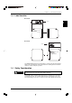
Appendices Appendix F Dimensions This section lists the dimensions of each model. ■ LS-5041 13 4-ø4.5 through-hole ø8 spot facing 4.5 (d) 4-M4 effective depth: 10 24 34 21 15 15 55 3-ø5.5 (Mounting hole) 17 55 Measurement range 3-ø5.5 (Mounting hole) 105 32 105 86 76 76 86 49 24 5 5 17 10 80 77 85 18 80 160 77 180 85 4-ø4.5 through-hole ø8 spot facing 4.5 (d) 5 4-M4 effective depth: 10 24 24 135 (9) 135 360 (9) 2-M4 17 17 2-M4 71 17 17 71 ■ LS-5001 1 37.
Appendices ■ LS-5121 4-ø6.5 through-hole ø14 spot facing 7 (d) 4-M4 effective depth: 10 35 55 20* 25 150 10 25 150 20±2 mm at the center of measurement area. 3-ø7.5 (Mounting hole) 32 3-ø7.5 (Mounting hole) 155 175 Measurement range 17 168 180 180 186 89 65 45 40 6 6 200 15 29.5 20 125 200 27.5 15 145 4-M6 effective depth: 10 8-ø4.5 through-hole ø10 spot facing 4.5 (d) 10 35 272 288 (16) 706 4-M4 effective depth: 6 10 4-M4 effective depth: 6 (16) 10 35 35 112 21.5 221.
Appendices Appendices 124
WARRANTIES AND DISCLAIMERS (1) KEYENCE warrants the Products to be free of defects in materials and workmanship for a period of one (1) year from the date of shipment. If any models or samples were shown to Buyer, such models or samples were used merely to illustrate the general type and quality of the Products and not to represent that the Products would necessarily conform to said models or samples.
Copyright (c) 2012 KEYENCE CORPORATION. All rights reserved.