LS-3100(W) Series 96M10280 Instruction Manual Laser Scan Micrometer LS-3100(W) Series 2010 10279E 1030-1 96M10280
SAFETY PRECAUTIONS This manual describes how to install the LS-3100(W) Series as well as its operating procedures and precautions. Please read this manual carefully to get the best from your LS-3100(W) Series. Symbols The following symbols alert you to important messages. Be sure to read these messages carefully. WARNING Failure to follow instructions may lead to injury. (electric shock, burn, etc.) CAUTION Failure to follow instructions may lead to product damage.
Unpacking Check that the following items are included in your LS system package. • Controller ....................................................................................... 1 • Scanning head ............................................................................... 11. • Laser beam cover (attached to scanning head) ............................ 11. • Connection cable ........................................................................... 31. • Power cable ..................................
CONTENTS Chapter 1 Laser Safety Precautions 1 1-1. Classification ............................................................................................... 1 1-2. Warning Labels ........................................................................................... 1 1-3. Label Location ............................................................................................. 2 1-4. Safety Consideration ...................................................................................
AVE Key .................................................................................................... 21 Averaging Methods ........................................................................ 21 PRM Selector Key ..................................................................................... 22 Analog Voltage Range ................................................................... 22 LIMIT ...................................................................................................
Chapter 7 Hints on Correct Use 76 Chapter 8 Error Messages 78 H-Err .................................................................................................................. 78 P-Err .................................................................................................................. 78 CALIB ERROR .................................................................................................. 78 Chapter 9 Troubleshooting Guide 80 Troubleshooting Guide .....................
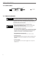
CHAPTER 1 LASER SAFETY PRECAUTIONS 1-1. Classification LS-3034 LS-3033 LS-3032 LS-3033 LS-3036 LS-3060 SO(8073) Laser FDA (CDRH) 21CFR Class Part 1040.10 IEC60825-1 DIN EN 60825-1 Class I Class II Class 1 Class 1 1-2. Warning Labels 1) Warning label FDA Class II CAUTION LASER RADIATION-DO NOT STARE INTO BEAM SEMICONDUCTOR LASER 670nm MAXIMUM OUTPUT 0.5mW CLASS II LASER PRODUCT 2) Aperture label FDA Class II AVOID EXPOSURE LASER RADIATION IS EMITTED FROM THIS APERTURE.
CHAPTER 1 Preparation for Measurement 1-3. Label Location 1) 2) AVOID EXPOSURE CAUTION LASER RADIATION-DO NOT STARE INTO BEAM SEMICONDUCTOR LASER 670nm MAXIMUM OUTPUT 0.5mW CLASS II LASER PRODUCT LASER RADIATION IS EMITTED FROM THIS APERTURE. : Aperture CAUTION-Laser radiation when open. DO NOT STARE INTO BEAM. 1-4 Safety Consideration CAUTION Use of controls or adjustments or the performance of procedures other than those specified herein may result in hazardous radiation exposure.
CHAPTER 1 Preparation for Measurement 1-5 Safety Features Provided with the LS-3100(W) Series The LS-3100(W) series has the following safety features: ■ Laser ON alarm LED Both the sensor head and the controller panel have a visible LED that lights when laser is ready to be and is being emitted. LEDs can be checked to see if they are lit even when you are wearing laser protective glasses.
CHAPTER 1 Preparation for Measurement 1-6. Preparation for Operation CAUTION • Do not mount the scanning head to the place where a certain level of electrical noise is applied or transferred. Isolate the scanning head if electrical noise may be occured. Otherwise, laser diode may deteriorate or become damaged. • Although the LS controller has been thoroughly inspected before shipment, we kindly request that you check it upon purchase for any damage.
CHAPTER 1 Preparation for Measurement 2. Ground the controller. (Except for models followed with “W”.) Grounding the controller to the grounding bar 3. Check first that the power switch of the controller is OFF, then connect it to the outlet using the supplied power cable. Controller (rear view) LS-3100 Series Grounding the controller through the grounding outlet LS-3100(W) Series I O 4. Check that laser can be safely emitted, then turn the power switch ON.
CHAPTER 1 Preparation for Measurement 1-7. Connecting 2 Scanning Heads CAUTION Do not connect or disconnect any cables while the power is ON. Otherwise, the laser diode may deteriorate and/or may be damaged. Note the following for connecting 2 scanning heads to the controller: • These heads have been factory-set for use either as the HEAD1 or HEAD2. Incorrect connection of the scanning heads will, therefore, result in malfunction. To prevent this, first check the serial No.
CHAPTER 2 TRIAL OPERATION 1. Connect the controller and scanning head(s). Make sure that the optical axis of the transmitter and receiver are aligned before turning the power ON. Aligning the optical axis is not necessary, however, when using the single-body type scanning head or when the transmitter and receiver are secured on the detachable frame. 2. Laser emission starts in approximately 5 seconds. 3. Make sure that the target is correctly positioned in the measurement area.
CHAPTER 3 Quick Setup Procedures CHAPTER 3 QUICK SETUP PROCEDURES The LS Series is a multi-function, versatile laser scan micrometer. This chapter describes the procedures for setting the LS-3100(W)/3101(W) by illustrating typical applications. This chapter covers the procedures needed to make measurements after the memory is initialized (after "MEMORY INITIALIZED" is displayed). Initializing Current Settings ...........................................................................
CHAPTER 3 Quick Setup Procedures How to Use This Chapter The switches on the left side of the front panel are shown on the left side of the pages in this chapter. All massages on the sub-display are shown on the right side of the pages in this chapter. The switches on the right side of the front panel are shown at the center of the pages in this chapter. 3-1. Common Settings Setting the Number of Measurements for Averaging See page 93 for Measurement Procedures.
CHAPTER 3 Quick Setup Procedures Tolerance Settings The following procedure shows how to set the upper limit to 10.5 mm, and lower limits to 9.5 mm. 6 0 – 6 0 . . 0 0 0 0 0 0 0 0 1 H I = L O = [ – 6 0 . 1 ] 0 0 0 0 0 H I = L O = [ – 6 0 . 1 0 ] 0 0 0 0 . H I = L O = [ – 6 0 . 1 0 . ] 0 0 0 0 5 H I = L O = [ – 6 0 . 1 0 . 5 ] 0 0 0 0 ENT H I = L O = 1 0 – 6 0 . . 5 0 0 0 0 0 0 0 H I = L O = 1 0 . 5 0 0 0 [ 9 H I = L O = [ .
CHAPTER 3 Quick Setup Procedures Gap Measurement 1 (When part of the target is outside the optical axis) ■ Applications • Measuring gap between rollers in a copy machine • Measuring gap between magnet roller and doctor blade T R ■ Setting 1. Initialize settings ("MEMORY INITIALIZED" is displayed.) 2.
CHAPTER 3 Quick Setup Procedures ■ Applications • Detecting uneven rubber roller in a copying machine • Detecting uneven rubber roller on a printer Measuring Roundness (When target is rotating) T R ■ Setting 1. Initialize settings ("MEMORY INITIALIZED" is displayed.) 2. MODE M O D E N O R M A L SET M O D E P – P OK When the measurement mode is set to "P-P", the displayed value is retained until HOLD is pressed or until an external signal is input through the hold synchronous input terminal. 3.
CHAPTER 3 Quick Setup Procedures When the measurement mode is set to "P-P", the displayed value is retained until HOLD is pressed or until an external signal is input through the hold synchronous input terminal. 3. Resetting displayed values (When 1. 2 3 4 5 appears on the main display) HOLD Main display HOLD Measuring Target Displacement within the Measuring Range HOLD The displayed value is reset to "0".
CHAPTER 3 Quick Setup Procedures 3.3 Using LS-3100D(W) Controller with 2 Scanning Heads Measuring Outer Diameters in the X and Y Axes The LS-3100D(W) uses 2 scanning heads for this measurement. ■ Applications • Measuring outer diameter of coated wire in the X and Y axes • Measuring outer diameter of extrusion molded parts ■ Setting 1. Initialize settings 2.
CHAPTER 4 FUNCTIONS AND CONTROLS 4-1. Part Names Controller Model: LS-3100(W)/3100D(W) 1 Front Panel LS-3100 Series 2 3 4 5 6 LIMT HIGH LS LASER mm GO LOW 1 LASER inch 2 OFFSET ZERO HOLD LOCK POSITION LASER SCAN DIAMETER SEG MODE SET 7 8 9 ZERO K AVE LIMIT OFS 4 5 6 HOLD L PRM FNC CAL 1 2 3 CLR M PROG DISP 0 .
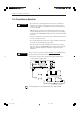
CHAPTER 4 Functions and Controls Back Panel P O R Q S T Model: LS-3100 CONTROL I/O RS - 232C HEAD 1 HEAD 2 MON GND P1 2 3 1 4 5 P2 P3 P4 P5 6 7 8 9 85~264V AC LASAER REMOTE PROGRAM SELECT TIM OV HIGH GO LOW GND 10 11 12 13 14 15 16 17 18 19 2A Model: LS-3100(W) U V P Q O W X R Y [ S \ T CONTROL I/O RS - 232C HEAD 1 Z HEAD 2 MON OV 1 PROGRAM SELECT TIM GND P1 2 3 4 5 P2 P3 P4 P5 6 7 8 9 LASAER REMOTE 85~264V AC HIGH GO 10 11 12 13
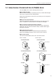
CHAPTER 4 Functions and Controls Model: LS-3032/3034/3036 9 E F SCANNING AREA 0 SCANNING AREA LS-3032 Model: LS-3033/3033 SO A 9 B SCANNING AREA E D C SCANNING AREA LS-3033T LS-3033R F 9 Protective cover glass To prevent lens from being damage or dust from accumulating on the lens surface (Spares are available for replacement.
CHAPTER 4 Functions and Controls 4-2. Indicators and Displays 2 1 LIMIT HIGH LS LASER GO 1 LOW LASER 2 LASER SCAN DIAMETER 1 Laser Emission Indicator LEDs Light when laser is being or about to be emitted from the scanning head. Only LED [1] lights when one scanning head is used. Both LED [1] and LED [2] light when two scanning heads are used. 2 Comparator Output LEDs Three LEDs, HIGH, LOW, and GO, are provided.
CHAPTER 4 Functions and Controls 4-3. Panel Keys C 2 SEG MODE SET 7 8 9 ZERO 8 AVE LIMIT OFS 4 5 6 HOLD 7 9 PRM FNC CAL 1 2 3 CLR 3 G PROG DISP 0 . +/- ENT B 1 Numeric Keys 6 A 0 E 5 F D 4 1 Enter numbers, a decimal point, and + or - sign. See the following examples: • Entering +10.0000 1 0 0 . 0 0 0 7 8 9 4 5 6 1 2 3 0 . +/- May be defaulted • Entering -10.0000 +/- 1 0 .
CHAPTER 4 Functions and Controls Registers the desired number. 4 ENT Key Turn ON the power while pressing and holding ENT to return to the factory settings. ➪ See P.89 to P.96 for the factory settings. 5 UP/DOWN Key When making certain settings, two of the following items, value, mode or ON/ OFF status, appear at the same time on the subdisplay (CH2). Press this key to move the cursor up and down to change one of the preset value or status. 6 ZERO (Auto-Zero) Key Resets the displayed value to "0". 1.
CHAPTER 4 Functions and Controls 8 AVE Key Sets the desired number of measurements and averaging method. (Selector key for number of measurements for averaging and averaging method) 1. Use AVE to display the current number and method. 2. To change the number of measurements, use UP/DOWN to move the cursor up. Then, use SET to specify the number. Each time you press SET, the number will increment in the following order: "1, 2, 4, 8 ••••• 512, and 1024".
CHAPTER 4 Functions and Controls 9 PRM Selector Key Displays sequentially the following 9 items: preset analog range, "LIMIT", "DIGIT SUPPRESS", "HOLD", "BAUD RATE", "UNIT", "BUZZER", "HEAD2", and "POSITION CHECK". Display the desired item first and make the necessary changes. See the instructions below for making settings in each item. Analog Voltage Range In this mode, measured value is converted into an analog voltage between -6 V and +6 V.
CHAPTER 4 Functions and Controls Example of Operation You are to measure the diameter of round bars. The reference diameter is 10 mm, and you wish to convert a difference of 1 mm into 1 V. In this case, first set 100.000 mm to 0 V. Then, to represent each 1 mm change in diameter from the reference by 1 V, set the reference plus 6 mm to +6 V and the reference minus 6 mm to -6 V. That is, +6 V = 16 mm and -6 V = 4 mm. Note Step Key operation 1 Use PRM to display analog voltage range.
CHAPTER 4 Functions and Controls Tolerance Limits and Comparator Output ■ 3-step differentiation Choose the 3-step differentiation first, then set the tolerance limits using LIMIT. When "ON" appears on the display, the comparator output is sent through each of the relays and open-collectors (HIGH, GO, or LOW). ➪ See P.63, 64 Tolerance limit Condition Output (Relay) (Open-collector) HI < X HIGH HI1 (CH1) HI ≥ X ≥ LO GO GO (CH1) X < LO LOW LO1 (CH1) HI LO Note: X represents a measured value.
CHAPTER 4 Functions and Controls ■ Switching between 3-step and 7-step differentiations 1. Use PRM to display "LIMIT" (on the subdisplay). Procedure 2. To switch between two types of differentiation, use UP/DOWN to move the cursor up. L I MI T 7CL ASSES ON 3. Each time you press SET, "7 CLASSES" and "3 CLASSES" are displayed alternately. Choose the desired type of differentiation. ■ Turning comparator output function ON/OFF 1. Use PRM to display "LIMIT" (on the subdisplay). 2.
CHAPTER 4 Functions and Controls Example of Operation You are to measure the diameter of round bars. The reference diameter is 10 mm. You wish to perform a 7-step differentiation with the following tolerance limits: ±0.1 mm, ±0.2 mm, ±0.3 mm. Step 1 Key operation Press PRM to display "LIMIT". L I MI T 3CL ASSES ON Use UP/DOWN to move cursor up. L I MI T 3CL ASSES ON 3 Use SET to display "7 CLASSES". L I MI T 7CL ASSES ON 4 Press PRM to display "HI1" and "LO1".
CHAPTER 4 Functions and Controls Procedure 1. Use PRM to display "DIGIT SUPPRESS" (on the subdisplay). D I G I T SU PPRE S S CH 1 CH 2 0 0 2. Use UP/DOWN to move the cursor up or down, then use SET to choose how many fractions you wish to delete. Each time you press SET, the subdisplay will show "0", "1", "2", "3", "4", and "0" again. 3. Note that they represent the number of digits to be deleted starting from the rightmost (smallest) fraction. HOLD Selects whether to use HOLD function (see P.
CHAPTER 4 Functions and Controls BUZZER Turns ON/OFF the beep during panel key operation. Procedure 1. Use PRM to display "BUZZER" (on the subdisplay). BUZ ZER ON 2. Use SET to display "ON" or "OFF". HEAD2 Selects whether to use two scanning heads or not. Procedure 1. Each time you press SET, "ON" and "OFF" are displayed alternately. 2. Display "ON" to use two scanning heads or "OFF" to use just one head.
CHAPTER 4 Functions and Controls 0 LIMIT (Tolerance limits for 3-step differentiation) Key This key is used to set the tolerance limits (upper and lower) for measured values on the main display (CH1). If the measured value is above the upper or below the lower limit, the comparator output is sent through the corresponding relay and open-collector. Procedure 1. Use LIMIT to display the current tolerance limits. ➪ See P.24 for the relationship between the tolerance limits and types of output obtained.
CHAPTER 4 Functions and Controls A SEG (Segment) Key Targets placed within the measurement area interrupt the passage of the laser beam, thus creating a light-dark pattern. The border between the light and dark regions is referred to an "edge". Also, each dark or light region separated by the edge is called a "segment".
CHAPTER 4 Functions and Controls Procedure 1. Press SEG to display the current segment pair (on the subdisplay). SEG DI A 2. Each time you press SET, the subdisplay will sequentially show "DIA", "EDGE1", "EDGE2", "(m,n)", then "DIA" again. Display the desired segment pair. You do not need to press any other key. (When two scanning heads are used, the subdisplay will sequentially show "DIA", "EDGE1", "EDGE2", "(m,n)", "2:DIA", "2:EDGE1", "2:EDGE2", "2:(m,n)", and "DIA" again.) 3.
CHAPTER 4 Functions and Controls Note • If you enter invalid numbers (other than 1 through 126) and press ENT, the initial edge numbers will remain on the subdisplay. • Basically, two numbers are entered in this mode. If by mistake you enter the larger number on the left and smaller number on the right, and press ENT, the smaller number will appear on the left and larger number on the right.
CHAPTER 4 Functions and Controls Procedure 1: Measuring 2 Segments with 1 Scanning Head 1. Use FNC to display the current segments for X and Y. X= Y= DI A DI A 2. Use UP/DOWN to move the cursor up. 3. Each time you press SET, "DIA", "EDGE1", "EDGE2", "(m,n)", and "DIA" will sequentially appear on the right of "X=". Display the desired segment. * "m" and "n" in (m,n) represent two desired edge numbers. X= Y= DI A ED G E I 4.
CHAPTER 4 Functions and Controls 4 5 Procedure 2: Using 2 Scanning Heads Use UP/DOWN to move cursor down. When you have selected "DIA" in step 3, use SET to display "Y= EDGE1". When you have selected "(m,n)" in step 3, enter 1 for "m" and 2 for "n", and press ENT. X= Y= DI A DI A X= Y= ( ( X= Y= DI A ED G E I X= Y= ( ( 2 , 1 , 2 , 1 , 3 2 ) ) 3 2 ) ) Press PRM first, and check that "HEADS2 ON" is displayed on the subdisplay. 1. Use FNC to display current segments. 2.
CHAPTER 4 Functions and Controls 4 Use UP/DOWN to move cursor down. 5 Segment selector Y Note Use SET to display "Y=2:DIA". X= Y= DI A DI A X= Y= DI A 2 : DI A • Some combinations of segments cannot be used with the LS controller. See the table below. ("✓" indicates valid combinations.
CHAPTER 4 Functions and Controls Procedure Check first that segment pair, (m,n), has been selected. 1. Use FNC to display "X SEG CHECK OFF". X SEG CH ECK OF F 4 2. Use SET to display "ON" on the right of "SEG CHECK" to activate the segment check mode. X SEG CH ECK ON 4 * When the currently selected segment pair is DIA, EDGE1, or EDGE2, "Y SEG CHECK" will be displayed. 3. Enter the correct number of edges. 4. Press ENT to register. 5. Press FNC to display "Y SEG CHECK OFF". 6. Repeat steps 3 and 4.
CHAPTER 4 Functions and Controls The LS controller is equipped with two output channels (CH1 and CH2) having their own displays and output terminals for simultaneous 2-point measurement. In this mode, you are to select which output channel to display or output each of the measured values for X and Y. You can also choose to select the equation containing X and Y as variables and obtain the result.
CHAPTER 4 Functions and Controls Equation -X -Y X+Y X-Y (X+Y)/2 (X-Y)/2 -(X+Y) -(X+Y)/2 Display or output Negative X or Y value, or Remainder of OFFSET value from which X or Y is subtracted (if OFFSET value is registered) Addition of X and Y Subtraction of Y from X Average of X and Y Subtraction of Y from X, then division by 2 Addition of X and Y, and negative of this result, or Negative remainder of OFFSET value from which addition of X and Y is subtracted (if OFFSET value is registered) Negative averag
CHAPTER 4 Functions and Controls 8 Use SET to display "CH1=X" 9 Use UP/DOWN to move cursor down. 10 CH1= X CH2= X+ Y CH1= X CH2= X+ Y Use SET to display "CH2=Y". CH1= X CH2= Y After step 10, each time you press FNC, the subdisplay will show the current measurement mode (one of NORMAL, P-P, PEAK, BOTTOM), OFFSET value, and tolerance limits. Be sure to select the parameters for CH2 in the same manner as you do for CH1.
CHAPTER 4 Functions and Controls Example of Operation Continued from P.39, you are to select "P-P" for measurement mode and "0.1 mm" for tolerance upper limit. By selecting 0.1 mm, the comparator output will be sent through CH2 if the measured value is above this limit. Step 11 Key operation Press FNC once to display current mode. 12 Use SET to display "P-P". 13 14 15 16 17 Use FNC to display current OFFSET value. Do not change OFFSET value. Press FNC again to display current tolerance limits.
CHAPTER 4 Functions and Controls • "Specified period" refers to the duration of time from when a measurement mode is set until when the mode is cancelled by pressing HOLD or inputting a signal through terminal TIM. • Use FNC to set the measurement mode for CH2. ➪ See P.39. 1. Press MODE to display the current measurement mode. Procedure MOD E NORMA L 2. Each time you press SET, the subdisplay will show sequentially "NORMAL", "P-P", "PEAK", and "BOTTOM". Display the desired mode.
CHAPTER 4 Functions and Controls 6. Press CAL to calibrate segment selector Y. "CAL Y" will appear on the subdisplay. You can display "CAL Y" by pressing CAL either when "CALIB OK" appears or when "CAL X" has just been displayed by pressing CAL. ("CAL X" and "CAL Y" display alternately each time you press CAL.) CA L Y 0 . 000 0 0 . 000 0 7. Repeat steps 2 to 5 just as you do for calibrating segment selector X. 8.
CHAPTER 4 Functions and Controls 4 Enter "20.1000". 5 Press ENT to register. "CALIB OK" will appear. CA L I B Press CAL to display "CAL Y". CA L 6 7 E DISP (Subdisplay) Key CA L X 1 0 . 010 0 [ 2 0 . 100 0 ] OK Y 0 . 000 0 0 . 000 0 Repeat steps 2 to 5 to calibrate Y.
CHAPTER 4 Functions and Controls You are to measure the diam- eter of a round bar. This diameter, supposedly 100 mm, is displayed and output in absolute value. HEAD1 Edge1 X Edge2 D HEAD2 Edge1 Y Edge2 Transmitter Receiver Place two scanning heads as shown above.
CHAPTER 4 Functions and Controls G PROG (Program) Key The LS controller can store the currently displayed settings. Up to 10 types of settings can be stored with each assigned a program number. Each type of settings can be retrieved through its program number for quicker operation. * BAUD RATE, BUZZER ON/OFF, HOLD type, HEAD2 ON/OFF, and POSITION CHECK cannot be stored. Storing (SAVE) Settings 1. Enter the desired parameters. 2. Press PROG to display "PROG". P R OG 1 LOAD SAVE 3.
CHAPTER 4 Functions and Controls Retrieving (LOAD) Settings 1. Press PROG to display "PROG". 2. Enter the desired program No. P R OG 1 LOAD SAVE 3. Press ENT to accept. At this moment, only the program No. has been selected. 4. Use ON/OFF to move the cursor up to "LOAD". 5. Press SET to display "LO OK?". Press ENT to accept or CLR to cancel. P R OG 2 LO OK ? SAVE 6. When you press ENT, the settings stored under the specified program No. will be retrieved. 7.
CHAPTER 4 Functions and Controls Table of I/O Terminals Analog Voltage Output Analog voltage signal for CH1 can be obtained through the MON terminals. The LS controller has been factory-set to convert a range from -60 mm to +60 mm into a voltage range from -6 V to +6V. (No voltage signal is provided for CH2. If voltage signal for CH2 is required, consult the KEYENCE distributor.) Analog voltage range: A range between -6 V and +6 V can be set to match a desired measurement range. Any value between -999.
CHAPTER 4 Functions and Controls Program Selector Input Terminals The desired program No. can be selected from external equipment using the following terminals: program selector input: Programs 1 to 5 selectable terminals #2 to #11: Programs 1 to 10 selectable (program selector input) Note that when two or more terminals are grounded at the same time, the program with the smallest number will be selected.
CHAPTER 4 Functions and Controls 4-4. I/O Terminal RS-232C I/O Terminal The LS controller is provided with the RS-232C interface, which allows the LS controller to communicate with an external computer. Data transmission or change of the settings can be remotely performed. Specifications The LS controller employs the RS-232C interface (recommended standard by EIA: Electronic Industries Association) for data transmission. LS controller is defined as "MODEM".
CHAPTER 4 Functions and Controls Connector Pin Assignment Use straight type cable. Connection example 1 Pin No. (PC) 1 2 3 5 6 7 8 20 Pin No. (LS) 1 2 3 5 6 7 8 20 Connection example 2 In addition to the pin connections shown here, all identically-numbered pins of PC and LS controller can be connected. 1 1 2 2 . . . . . . O O Pin No. Pin No.
CHAPTER 4 Functions and Controls [COMMAND] List Function Specifying segment check Command SS SR Nn LDn Description Specifies segment check ON Specifies segment check OFF Specifies the number of segments ("n") for segment check Specifies DIA Specifies EDGE1 Specifies EDGE2 Specifies values ("m" and "n) for SEG (m, n) (m < n) Sets 1 Sets 2 Sets 4 Sets 8 Sets 16 Sets 32 Sets 64 Sets 128 Sets 256 Sets 512 Sets 1024 Sets simple (SIMPLE) averaging Sets sequential (MODE) averaging (Valid only when the number
CHAPTER 4 Functions and Controls Entry Examples • To specify "1" for program No., "Y" for segment selector, "1" for scanning head No., and SEG (3, 4) for measurement segment: "P1Y1S3,4 CR" • To specify "2" for program No., "X" for segment selector, and "OFF" for segment check: "P2XSR CR" • To specify "3" for program No., "X" for segment selector, "1" for scanning head No.
CHAPTER 4 Functions and Controls Commands for setting functions Function Setting arithmetic operation method Command C0 C1 C2 C3 C4 C5 C6 C7 C8 C9 Setting MN measurement mode MP ME MB Setting tolerance Hn range for 3-level differentiation Ln Setting OFFSET value Setting display digit deletion On Gn Description Sets method "X" Sets method "Y" Sets method "X+Y" Sets method "X-Y" Sets method "(X+Y)/2" Sets method "(X-Y)/2" Sets method "-X" Sets method "-Y" Sets method "-(X+Y)" Sets method "-(X+Y)/2" Sets
CHAPTER 4 Functions and Controls Output of Measurement Data Specifies the output method of the processed measurements which are displayed on the main display (CH1) and sub-display (CH2), and outputs them according to the specified method.
CHAPTER 4 Functions and Controls Output of Setting Status Specifies and outputs the setting status of the desired program. The format differs with the setting information to be output, as described below. Format: ( [P$] [Ø$] ) [COMMAND] CR Output Channel Program No. Note that one or both of the commands in ( ) can be omitted. When [P$] is omitted, the current program No. will be valid. When [Ø$] is omitted, CH1 will be specified. [P$] [Ø$] List Function Specifying program No.
CHAPTER 4 Functions and Controls Function Specifying and outputting setting information Command Description TF? Outputs preset value of LOW1 for 7-level differentiation I? Outputs whether comparator output is set to ON or OFF T? Outputs differentiation level (3- or 7-level) AS? Outputs preset value for analog output voltage scaling A? Outputs preset value for number of measurements for averaging B? Outputs averaging method (simple or sequential ) U? Outputs measurement unit ( "mm" or "inch" ).
CHAPTER 4 Functions and Controls The output data format from the controller is as follows: Output data format ● Segment selector When DIA is specified: 1st data 2nd data 3rd data 4th data D I A CR When EDGE1 is specified: 1st data 2nd data 3rd data E D G 4th data E 5th data 1 6th data CR When SEG (1, 2) for the 2nd scanning head is specified: 1st data 2nd data 3rd data 2 : S 4th data 0 5th data 0 6th data 7th data 1 , 8th data 9th data 0 0 10th data 9th data 2 CR ● Segment
CHAPTER 4 Functions and Controls ● Number of measurements for averaging When 16 is set: 1st data 2nd data 3rd data 1 6 CR When 1,024 is set: 1st data 2nd data 3rd data 1 0 2 4th data 5th data 4 CR ● Averaging method When simple averaging is set: 1st data 2nd data 3rd data S I M 4th data 5th data P L 6th data E 7th data CR When sequential averaging is set: 1st data 2nd data 3rd data M O V 4th data 5th data E CR ● Measurement unit When "mm" is set: 1st data 2nd data 3rd data
CHAPTER 4 Functions and Controls ● HOLD function (ON or OFF) When HOLD function is set to ON: 1st data 2nd data 3rd data O N CR ● Arithmetic operation method When "X" is set: 1st data 2nd data X CR When "X+Y" is set: 1st data 2nd data 3rd data 4th data X + Y CR When "(X+Y)/2" is set: 1st data 2nd data 3rd data ( X 4th data + 5th data ) Y 6th data / 7th data 2 8th data CR ● Measurement mode When NORMAL is set: 1st data 2nd data 3rd data N O 4th data R M 5th data A 6th data
CHAPTER 4 Functions and Controls ● Display digit suppress function When the number of suppressed display digits is 0: 1st data 2nd data 0 CR When the number of suppressed display digits is 3: 1st data 2nd data 3 Program Example in BASIC CR Program 1 Pressing the space key of the computer allows the measured values to appear on the computer display.
CHAPTER 4 Functions and Controls Program 3 The following settings are specified through the computer: simultaneous measurement of DIA and EDGE1, 100 samplings for each of DIA and EDG1, and display of maximum, minimum and average values of these measurements.
CHAPTER 4 Functions and Controls 36-pin Connector (Control I/O) Output • TTL open-collector (7406 or equivalent) • Max. applicable voltage: 30 V • Max. sink current: 40 mA Specifications Input • TTL voltage level, negative logic (74LS19 or equivalent) 17 18 IN 62 3K Ω IC 6.2K Ω H 1 Z I Signal Pin No. GND 19 Program No. 1 selector input: P1 20 Program No. 2 selector input: P2 21 Program No. 3 selector input: P3 22 Program No. 4 selector input: P4 23 Program No.
CHAPTER 4 Functions and Controls Program (No. 1 to 10) selector input: P1 to P10 • Used to select the desired program from external equipment. Input Signal • When pin 2 (3, 4, ••• or 11) is grounded with GND for an instant, program No. 1 (2, 3, ••• or 10) is selected. • When two or more pins are grounded at the same time, the program with the smallest number will be selected. Synchronous input: TIM • When pin 12 (TIM) is grounded with pin 13, the measured value is retained.
CHAPTER 4 Functions and Controls Control Input Terminals Internal circuit Input specifications +12V Photocoupler 1.8 kΩ 680 Ω Control input terminals GND Example of connection •Contact (relays or switches) LS controller Control input terminals GND Hold Synchronous Input Terminals •Solid-state (transistors) LS controller Open-collector output Control input terminals GND • When terminal 3 is grounded with terminal 4, the displayed and output values are retained.
CHAPTER 5 MOUNTING SCANNING HEAD 5-1. Alignment of Optical Axis (LS-3060 and LS-3033 only) The LS-3060 is delivered with the transmitter and receiver (scanning head) mounted to the detachable frame. When using the LS-3060 with the transmitter and receiver removed from the frame on when using the LS-3033, be sure to align them in terms of the optical axis of the laser. (See the figure below.) Misalignment of the optical axis will cause measurement errors.
CHAPTER 5 Mounting Scanning Head 5-2. Checking Alignment of Optical Axis (LS-3033 and LS-3060 only) Not applicable to LS-3033 SO (8073). Use the POSITION CHECK function to check whether the transmitter and receiver (scanning head) are aligned in terms of the optical axis. The procedure is as follows: 1. Use PRM to display "HEAD1" and "POSITION CHECK" on the subdisplay. H EA D 1 P OS I T I O N CHECK 2. Attach the optical axis checker to the receiver. 3.
CHAPTER 5 Mounting Scanning Head In the POSITION CHECK mode, the target position indicator LEDs show whether the transmitter and receiver (scanning head) are aligned in terms of the optical axis. Error Messages (For Models LS-3060 and LS-3033) Display Description mm inch OFFSET LOCK POSITION The transmitter and receiver are aligned . 123 4 56 7 "GOOD" appears, and target position indicator LED 4 lights.
CHAPTER 6 OPTIONAL INTERFACE BOARDS The optional interface boards shown in this chapter can be factory-attached by the manufacturer at your request. 6-1. BCD Output Input TTL voltage level, negative logic (74LS19 or equivalent) Specifications +5V IN 3K Ω IC 6.2K Ω Output TTL voltage level, positive logic (74LS04 or equivalent) Pin Assignment IC H 1 Z I Pin No.
CHAPTER 6 Optional Interface Boards Output Signal • BCD positive logic signal that represents measured values Measured value is output every 20 ms when the MOVE averaging mode (number of measurements for averaging: 16 to 1,024) is set, or every "2.5 ms x number of measurements for averaging" when the SIMPLE averaging mode is set. BCD Output • When the measured value is negative, "1011" is output as the 103 digit. Strobe Signal (STROBE OUT) Negative logic signal with pulse width of approx.
CHAPTER 6 Optional Interface Boards External Trigger Input (EXT TRIG IN) When EXT TRIG IN is pulled low with ETE IN pulled low, the measured value is output after a max. of 20 ms (MOVE averaging, number of measurements for averaging: 16 to 1,024), or a max. of "2.5 ms x number of measurements for averaging" (SIMPLE averaging). The output value is retained until EXT TRIG IN is pulled low again. 6-2.
CHAPTER 6 Interface Functions Pin No. 17 Signal REN 18 19 20 21 22 23 24 GND (DAV) GND (NRFD) GND (NDAC) GND (IFC) GND (SRQ) GND (ATN) Logic GND Function Allows the controller to remotely enable or disable devices on the line.
CHAPTER 6 Optional Interface Boards Use the 1st to 5th DIP switches from the right (4, 5, 6, 7 and 8 in the figure) to set the address. Addresses "0" to "30" can be set. To set the address to "11", set the DIP switches as shown below. With the LS controller, the address has been factory-set to "0". ON Setting Address 1 2 3 4 5 6 7 8 Setting Talk Only Mode To set the LS controller to the talk only mode, set the 3rd DIP switch from the left (3 in the figure) to ON (down).
CHAPTER 6 Listener-talker Functions Setting Functions and Outputting Measured Values or Other Data Optional Interface Boards By sending commands from an external device (computer, etc.) to the LS controller, you can remotely set the various functions, or output measured values or other data from the LS controller. * For sending commands, ASCII character codes can be used. The commands and formats are the same as those for the RS-232C. See section "RS-232C" in this manual.
CHAPTER 6 Optional Interface Boards When the LS controller receives serial polling signal from the controller, the LS controller transmits a status byte. The content of the status byte is as shown below. Status Byte (MSB) (LSB) DI08 DI07 DI06 DI05 DI04 DI03 DI02 DI01 0 0 0 0 0 0 RQS bit Bit DI01 is set to "1" when syntax error occures Basic Sequence When 2 or more commands are transmitted, loop 1 is executed repeatedly.
CHAPTER 6 Optional Interface Boards Example of Program When connecting LS controller with external computer Program The following settings are specified through the computer: DIA (segment mode), CH1=X (output channel mode), NORMAL (measurement mode), MOVE (averaging mode), 512 (the number of measurements for averaging). Then, the measured value is displayed once on the computer.
CHAPTER 7 HINTS ON CORRECT USE • When noise interference may occur in the surroundings, connect the LS controller to an external device (computer, etc.) using an electromagneticinterference protection cable(s). Be sure to turn OFF the power of the LS controller before connecting it to an external device. General • Supply power to the computer or other device(s) before supplying power to the LS controller.
CHAPTER 7 Hints on Correct Use • With the LS series, the controller and scanning head are calibrated as a pair. To satisfy the specifications, therefore, be sure to combine a controller and scanning head having the same serial number. Compatibility • The transmitter and receiver are also calibrated as a pair. • When using 2 scanning heads, connect them respectively to the specified connector port of the controller.
CHAPTER 8 ERROR MESSAGES H-Err • If no scanning head is connected to the controller or the connected scanning head malfunctions, an error message appears on the main display (CH1). When 1 scanning head is used: If no scanning head is connected or the connected scanning head mal functions, "H-Err" appears.
CHAPTER 8 Error Messages 79 ls3100_76_88.p65 79 08.10.
CHAPTER 9 TROUBLESHOOTING GUIDE If any conditions occur that could be considered as equipment failure or malfunction, follow the inspection procedures given below. Check item Problem Measure- • Measured value is not ment displayed. value • Nothing appears on the display display. "------" is displayed. Details of inspection Corrective action • Is the power switch ON? • Turn ON the switch. • Is the AC power cable connected? • Connect the AC power cable.
CHAPTER 9 Check item Problem Details of inspection Measure- The measurement display • Are the targets correctly placed in the measurement value contains unusual ment area? dispersion. Value • Is a standard edge placed Display within the measurement area? • Is there any dust or dirt on the laser aperture? • Is there any dust or dirt on the targets? • Is there a large fluctuation of ambient temperature? Abnormal measurement values are being displayed.
CHAPTER 9 Check item Troubleshooting Guide Problem Computer Computer data is not output output. Details of inspection • Is the baud rate correctly set? Corrective action • Set the controller and computer to the same baud rate. Note, however, that some computers may not recognize correct measurements when set to a high baud rate. • Check that the cable connector is securely connected to the port. • Be sure to turn ON the computer first, then controller.
APPENDIX A OPERATING PRINCIPLE Laser beam emitted by semiconductor is reflected first by the polygonal mirror, then by the reflector mirror. Laser beam is scanned according to the rotational angle of the polygonal mirror during this process. Then, scanned beams pass through the collimator lens so that they run parallel to each other. These beams are directed at the target and converged onto a photodiode by another lens.
APPENDIX B CHARACTERISTICS Measuring Area vs. Accuracy Data LS-3033 LS-3032 Center of detecting area 10 4 Receiver Center of detecting area 30 20 30 20 Transmitter 20 10 Transmitter ± 2 µm ± 2 µm ± 5 µm 60 ± 5 µm When a rod 10 mm in diameter is measured. When a rod 10 mm in diameter is measured with a transmitter-toreceiver distance set to 120 mm.
APPENDIX B Temperature Characteristics (Typical) Characteristics When a rod 10 mm in diameter is measured at the center of the measuring area [reference temperature: 20°C (68°F)]. LS-3032 Temperature Drift 0°C (32°F) +2.2 µm 10°C (50°F) 20°C (68°F) 30°C (86°F) 40°C (104°F) +1.1 µm 0 -1.4 µm -3.2 µm LS-3033* Temperature Drift 0°C (32°F) +2.0 µm 10°C (50°F) 20°C (68°F) 30°C (86°F) 40°C (104°F) +0.8 µm 0 -1.0 µm -2.2 µm LS-3034 Temperature Drift 0°C (32°F) +2.
APPENDIX C SPECIFICATIONS Controller Type Multi-functional (for connecting 2 scanning heads) Model LS-3100(W) [LS-3100D(W)] Display Measured value Minimum display unit Display range Comparator output indicator Terminal block I/O Laser emission indicator 36-pin connector I/O 0.0001 mm (0.00001 inches) -999.9999 to 9999.
APPENDIX C Specifications Scanning Head Type Fine measuring Scanning head type Model Single-body Separate Single-body Separate Single-body Separate LS-3034 LS-3033 SO (8073) LS-3032 LS-3033 LS-3036 LS-3060 0.08 to 30 0.3 to 30 0.5 to 30 0.3 to 30 0.8 to 60 0.00315 to 1.18110 0.01181 to 1.18110 0.01969 to 1.18110 0.01181 to 1.18110 0.03150 to 2.36220 1. Unit: mm Measuring range Minimum target width Unit: in Unit: mm Unit: in T and R distance Light source 0.08 0.3 0.5 0.
APPENDIX D DIMENSIONS Controller LS-3100(W) R7.5 R11 244 230 330 111 126 126 13 25 Approx.34 11 10.6 30 10.8 230 24 Scanning Head LS-3032/3034/3036 8 25.2 17 50 186 LS-3033/3033 SO (8073) 12.5 (12) 38 38 26 12.5 38 (25.5) (25.5) 105.5 Detecting area 4 x ø4.5 mounting hole (30) (34) 105.5 4 x ø5.5 mounting hole 4 x ø5.5 mounting hole Measuring area (34) (30) Transmitter 83 72 51 56 73.5 85 46 30 6 Receiver 85 73.5 32 46 6 60 19.
APPENDIX E QUICK REFERENCE TABLE Modes (Function) and Key Operations • This table shows what keys are used to set parameters for each functions. • First, press the key indicated by once, then press the key indicated by twice or more to display the desired function. • See also the flowchart of each key for better understanding the status of settings at each step and also learning how to enter parameters. Output channel Mode Page AVERAGE (Number of measurements) P.
APPENDIX E Quick Reference Table Mode Page Output channel CH1 (main display) CH2 (subdisplay) SEGMENT CHECK PRM P.35 MODE (Measurement mode) CALIBRATION DISPLAY (Switching items on subdisplay) OFFSET P.40 FNC SET CAL CAL P.43 DISP DISP FNC NORMAL, P-P, PEAK, and BOTTOM are available. Segment selectors X and Y can be calibrated. For items that can be displayed, see P.89. FNC OFS P.45 Number of edges can be checked during measurement. PRM P.41 P.
APPENDIX F KEY FLOWCHARTS PRM (Parameter) Variable, parameter, or status in ( ) is to be set using a key in { }. Note that those in ( ) in this flowchart are factory settings. PRM +6 V = (60.0000) -6 V = (-60.0000) Numeric keys ENT PRM LIMIT (3) CLASSES (ON) SET 7-step differentiation PRM 3-step differentiation (Use LIMIT to enter numeric values.) DIGIT CH1 (0) SUPPRESS CH2 (0) SET HI1 = (10.0000) LO1= (-10.
APPENDIX F Key Flowcharts * Variable, parameter, or status in ( ) is to be set using a key in { }. Note that those in ( ) in this flowchart are factory settings. AVE (Average) AVE AVE 1024 (MOVE) SET SET AVE AVE 1 SIMPLE 2 SIMPLE AVE SET AVE AVE 4 SIMPLE SET 128 (MOVE) SET 256 (MOVE) SET 512 (MOVE) SET SET 8 SIMPLE AVE SET AVE 64 (MOVE) SET SET AVE SET SET SET AVE 32 (MOVE) SET 16 (MOVE) SET AVE SET SET 92 ls3100_89_96.p65 92 08.10.
APPENDIX F Key Flowcharts SEG (Segment) * Variable, parameter, or status in ( ) is to be set using a key in { }. Note that those in ( ) in this flowchart are factory settings. SEG SEG DIA SEG 2:DIA SET SET SEG 2:EDGE1 SEG EDGE1 SET SET SEG 2:EDGE2 SEG EDGE2 SET SET SEG (1. 2) SET Numeric keys When 2 scanning heads are used ENT SEG 2: (1. 2) Numeric keys ENT SET When 1 scanning head is used 93 ls3100_89_96.p65 93 08.10.
APPENDIX F Key Flowcharts * FNC (Function) Variable, parameter, or status in ( ) is to be set using a key in { }. Note that those in ( ) in this flowchart are factory settings.
APPENDIX F Key Flowcharts DISP (Display) MODE * Underlined modes and values vary according to the current settings and the values measured. Settings cannot be changed in the DISP mode. Note that the underlined values are factory settings. MODE DISP DIA NORMAL AVE 1024 MODE NORMAL DISP SET CH2 NOR 0.0000 MODE P-P DISP CH1 NOR SET 0.0000 MODE PEAK DISP CH1 P-P SET 0.0000 MODE BOTTOM DISP CH1 SET P 0.0000 B 0.0000 DISP 95 ls3100_89_96.p65 95 08.10.
APPENDIX F Key Flowcharts * PROG (Program) Variable, parameter, or status in ( ) is to be set using a key in { }. Note that those in ( ) in this flowchart are factory settings. PROG PROG(1) SET LOAD SAVE ENT When storing a program PROG 1 ENT Numeric keys PROG 1 LO ok? SAVE ENT Retrieving completed OFS (Offset) LOAD SA ok? Storing completed CAL (Calibration) CAL OFS CAL X OFFSET (0.0000) Numeric keys ENT (0.0000) (0.0000) Numeric keys ENT (0.0000) (0.
SAFETY PRECAUTIONS This manual describes how to install the LS-3100(W) Series as well as its operating procedures and precautions. Please read this manual carefully to get the best from your LS-3100(W) Series. The following symbols alert you to important messages. Be sure to read these messages carefully. Symbols WARNING Failure to follow instructions may lead to injury. (electric shock, burn, etc.) CAUTION Failure to follow instructions may lead to product damage.
LS-3100(W) Series 96M10280 Instruction Manual Laser Scan Micrometer LS-3100(W) Series 2010 10279E 1030-1 96M10280