
User Manual

4
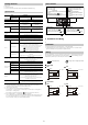
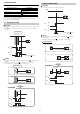
3-1. I/O Selection
Select from the following table the functions assigned to the I/O wires (black and white).
The functions assigned to output 1, output 2, and external input can be changed after you
finish configuring the initial settings. "6 Detailed Settings" (page 9).
* Would be fixed to transmission OFF.
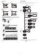
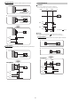
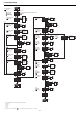
3-2. External Input Selection
Transmission OFF [Laser Off]
The laser beam transmission is stopped.
External Calibration [Tuning]
When selected, this external input performs the same function as pressing the [SET]
button.
Reference surface update [DATUM Preset]
When the detection mode ( "4 Detection Mode" [page 5]) is set to "DATUM mode," this
external input updates the reference surface.
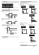
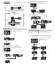
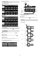
3-3. Analog Selection
Select from the following values.
• Current output: 4 to 20 mA
• Voltage output: 0 to 10 V
3-4. Analog Lower and Upper Limits
Configure scaling settings, if necessary.
Current output (4 to 20 mA)
z Initial settings z When settings are changed
(example)
For details on the analog output when an error occurs, see " Output When an Error
Occurs" (page 11).
■
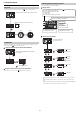
Voltage output (0 to 10V)
●
Initial settings
●
When settings are changed
(example)
For details on the analog output when an error occurs, see " Output When an Error
Occurs" (page 11).
3-5. NPN/PNP Selection
You can select between NPN outputs or PNP outputs. For details, see "Wiring" (page
2).
Options Black Wire White Wire
Out1 + Out2 Output 1 Output 2
Input + Out1 External input Output 1
Out1 + Analog Output 1 Analog output
Input + Analog External input* Analog output
Transmission TransmissionOFF
Input
ON
< 5 ms < 50 ms
OFF
Input
ON
> 60 ms
> 60 ms
OFF
Updated reference surface
Updated output
Input
ON
> 5 ms
< 60 ms
Response
time
OFF
20.5 mA
20 mA
4 mA
0 50 5000
3.8 mA
20.5 mA
20 mA
4 mA
0 2000 4000
3.8 mA
20.5 mA
20 mA
4 mA
0 2000 4000
3.8 mA
Analog 4 mA 0
Analog 20 mA 5000
Analog 4 mA 4000
Analog 20 mA 2000
Analog 4 mA 2000
Analog 20 mA 4000
10 V
0 50 5000
0 V
10 V
0 2000 4000
0 V
10 V
0 2000 4000
0 V
Analog 0V
2000
Analog 10V
4000
Analog 0V
4000
Analog 10V
2000
Analog 0V
0
Analog 10V
5000