
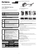
User Manual

3
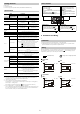
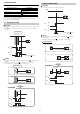
Out1+Analog
z NPN z PNP
Input+Analog
z NPN z PNP
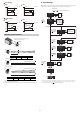
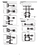
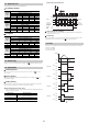
Adjusting the Spot Diameter
Narrow Spot Setting
Parallel Light Setting
Wide Spot Setting
• When detecting objects that have holes in them, you can perform stable detection by
making the spot diameter larger.
• Set the spot diameter so that it is 40 mm or less at the desired detecting distance.
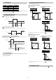
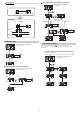
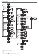
3 Initial Settings
When you turn on the LR-TB Series for the first time after you purchase it or when you have
initialized the LR-TB Series, the following initial settings must be configured.
•
After you have finished configuring the initial settings, you will not be able to reconfigure the
unit, I/O, analog selection, or NPN/PNP selection. To change any of these settings, you will
have to initialize the product . "Initialization" (page 8).
NARROW 1 2 3
X (Approx.) 500 1000 2000
WIDE5678
X (Approx.) 5000 3000 1500 750
1, brown
4, black
2, white
3, blue
20 ... 30 V
0 V
1, brown
4, black
2, white
3, blue
20 ... 30 V
0 V
1, brown
4, black
2, white
3, blue
20 ... 30 V
0 V
1, brown
4, black
2, white
3, blue
20 ... 30 V
0 V
1
2
3
4
5
6
7
8
WIDE
NARROW
Use the dial on the back of the sensor
to adjust the spot diameter.
1
2
3
4
5
6
7
8
WIDE
NARROW
0X mm
1
2
3
4
5
6
7
8
WIDE
NARROW
Diameter of approx. 6 mm
1
2
3
4
5
6
7
8
WIDE
NARROW
0 X mm
Diameter of approx. 40 mm
mm
inch
feet
and
Display Units
Press for 3 seconds or more
Start Config.
Select I/O
Select Input
Select Analog
Select Output
End Config.
RUN
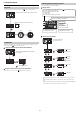
NPN
NPN
PNP
Analog Scaling
Analog Scaling
4 - 20 mA
20 mA = 5000
4 mA = 0
4 - 20 mA
0 - 10V
Laser Off
Laser Off
Tuning
DATUM Preset
Out1+Out2
Out1+Out2
Out1+Out2
Out1+Analog
Out1+Analog or Input+Analog
Input+Analog
Input+Out1
Input+Out1
1234
500
1
2
9999
0
...
9999
0
...
3-1. I/O
Selection
( page 4)
3-2. External
Input Selection
( page 4)
3-5. NPN/PNP
Selection
( page 4)
3-3. Analog
Selection
( page 4)
3-4. Analog
Lower Limit
( page 4)
3-4. Analog
Upper Limit
( page 4)